


Digital Port Functions 119
D
Digital Port Functions
Digital Connector
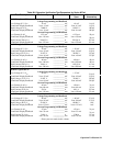
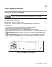
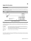
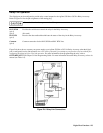
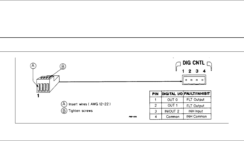
A 4-pin connector and a quick-disconnect mating plug are provided for digital input and output signals (see Figure D-l for
wiring connections, and Table 1-5 in Chapter 1 for electrical characteristics). This digital port can be configured to provide
either Fault/Inhibit or Digital I/O functions.
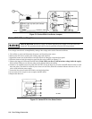
Note Consistent with good engineering practice, twist and shield all signal wires to and from the digital
connector.
Figure D-1. Digital Port Connector
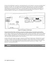
Fault/Inhibit Operation
As shipped from the factory, the digital port is configured to provide a fault indicator (FLT) output and a remote (INH)
input. Unplug the mating plug to make the connections. After you have finished making all connections, plug the wired plug
back into the connector.
FLT Output
(pins 1 and 2)
Used to indicate that a fault has occurred in power supply. Pins 1 and 2 are the open collector
output of an optocoupler, with pin 1 the collector and pin 2 the emitter. When a fault has occurred,
pin 1 is driven low with respect to pin 2 (negative-true).
INH Input (pin 3)
Used to shut down the power supply output. Pin 3 is a high impedance input. The supply shuts
down when this input is driven low (negative-true). This can be done by shorting pin 3 to pin 4.
INH Common
(pin 4)
Provides the common connection for the INH input.
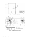
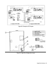
Three examples are provided to show how to use the FLT/INH circuits of your power supply. Use twisted wire connections
to reduce or prevent EM in all cases. If shielded wire is used, connect only one end of the shield to the chassis signal ground
binding post to prevent ground loops.