


Operation Verification 105
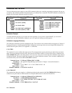
Performing The Tests
General Measurement Techniques
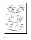
Figure B-1 shows the setup for the tests. Be certain to use load leads of sufficient wire gauge to carry the output current (see
Table 4-1). To avoid noise pickup, use coaxial cable or shielded pairs for the test leads.
Programming the Power Supply
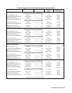
Table 1-lb, Table 1-2b, Table 1-3b and Table 1-4b in Chapter 1 list the programming voltage and current ranges for each
model. Enter the appropriate values from the front panel. The programming procedures assume you know how to operate
the power supply from the front panel (see "Chapter 5 - Front Panel Operation").
Order of Tests
Perform the following tests for operation verification. Test 1 must be done first, followed by Tests 2 and 3 in any order.
1 Turn-on Checkout
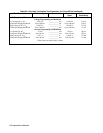
2 Voltage Programming and Readback Accuracy
3 Current Programming and Readback Accuracy
Turn-on Checkout
Perform the Turn-on Checkout as directed in "Chapter 3 - Turn-on Checkout".
Note The power supply must pass turn-on selftest before you can proceed with these tests.
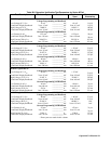
Voltage Programming and Readback Accuracy
This test verifies that the voltage programming, GPIB readback, and front panel display functions are within specifications.
Figure B-1 shows the setup for the tests. Measure the dc output voltage directly at the sense connections of the output
terminals or bus bars. Connect the output as shown.
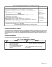
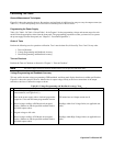
Table B-2. Voltage Programming and Readback Accuracy Tests
Action Normal Result
1 Turn off the power supply and connect a DVM across the
sense terminals (see Figure B-1(1)).
2 Turn on the power supply with no load and program the
output for 0 volts and maximum programmable current.
CV annunciator on. Output current near 0.
3 Record voltage readings at DVM and on front panel
display. (Subtract or add the specified readback limit to
the actual output values).
Readings within Low Voltage limits (see applicable test
table).
4 Program voltage to full scale.
5 Record voltage readings of DVM and on front panel
display. (Subtract or add the specified readback limit to
the actual output values)
Readings within High Voltage limits (see applicable test
table).