


2 - Installation
30
(256 channels)
(256 channels)
P
o
w
e
r
S
o
u
r
c
e
(
2
4
V
@
1
6
0
A
)
Powerbus Load
P
o
w
e
r
S
o
u
r
c
e
(24 V @ 160 A)
+
_
+
_
+
_
+
_
+
_
maximum
discharging
current = 196A
maximum
charging
current = 480A
+ -
charging = 240A
discharging = 98A
charging = 240A
discharging = 98A
discharging = 196A
charging = 160A
charging = 160A
+4 E4375A cards
(256 channels)
P
o
w
e
r
S
o
u
r
c
e
(
2
4
V
@
1
6
0
A
)
Powerbus Load
P
o
w
e
r
S
o
u
r
c
e
(24 V @ 160 A)
+
_
+
_
+
_
+
_
A
g
i
l
e
n
t
E
4
3
7
0
A
(256 channels)
+
_
+
_
T
e
r
m
i
n
a
l
B
l
o
c
k
STAR CONFIGURATION
Rigid Bars
Flexible Wires
BUS BAR CONFIGURATION
Flexible Wires
1
6
0
A
160A
1
9
6
A
2
40A/98A
2
4
0
A
/
9
8
A
A
g
i
l
e
n
t
E
4
3
7
0
A
A
g
i
l
e
n
t
E
4
3
7
1
A
A
g
i
l
e
n
t
E
4
3
7
1
A
A
g
i
l
e
n
t
E
4
3
7
0
A
A
g
i
l
e
n
t
E
4
3
7
0
A
+4 E4375A cards
+4 E4375A cards
+4 E4375A cards
P
o
w
e
r
S
o
u
r
c
e
(
2
4
V
@
1
6
0
A
)
+
_
charging = 160A
P
o
w
e
r
S
o
u
r
c
e
(
2
4
V
@
1
6
0
A
)
+
_
1
6
0
A
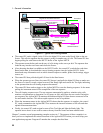
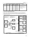
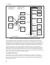
Charging values based on:
Power/channel = 18W
Efficiency = 80%
Power bus voltage = 24V
Discharging values based on:
Power/channel = 13.5W
Efficiency = 75%
Power bus voltage = 26.5V
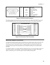
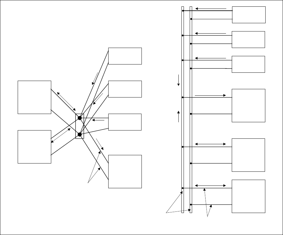
Figure 2-2. Typical Power Bus Configuration for Agilent E4375A cards
The star configuration on the left is designed so that each section of the power bus carries no more
current than the rating of the equipment that it is connected to. This configuration lets you use longer
lead lengths because the voltage drop in each lead is directly related to the amount of current flowing in
the lead. However, this configuration requires you to run separate leads from each Agilent MCCD
mainframe to the load as well as the power supply, thus increasing the total amount of wiring required.
The bus bar configuration on the right is designed to minimize the amount of wiring between the
equipment. However this requires larger diameter wires or bus bars. This is because the leads from the
power supplies as well as the leads to the load are required to carry the full charging and discharging
current for two Agilent E4370A MCCD mainframes. Larger currents result in larger voltage drops in the
wiring, which may prove unacceptable with long lead lengths.
Charging Mode Guidelines:
Power bus wires must be capable of handing the full charging current requirements of all Agilent
E4370A MCCD units connected to the power bus. In the example that follows, the calculations are for
worst case current requirements. Calculate the input current requirement of one fully loaded Agilent
E4370A MCCD as follows: