General Information
16
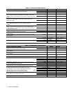
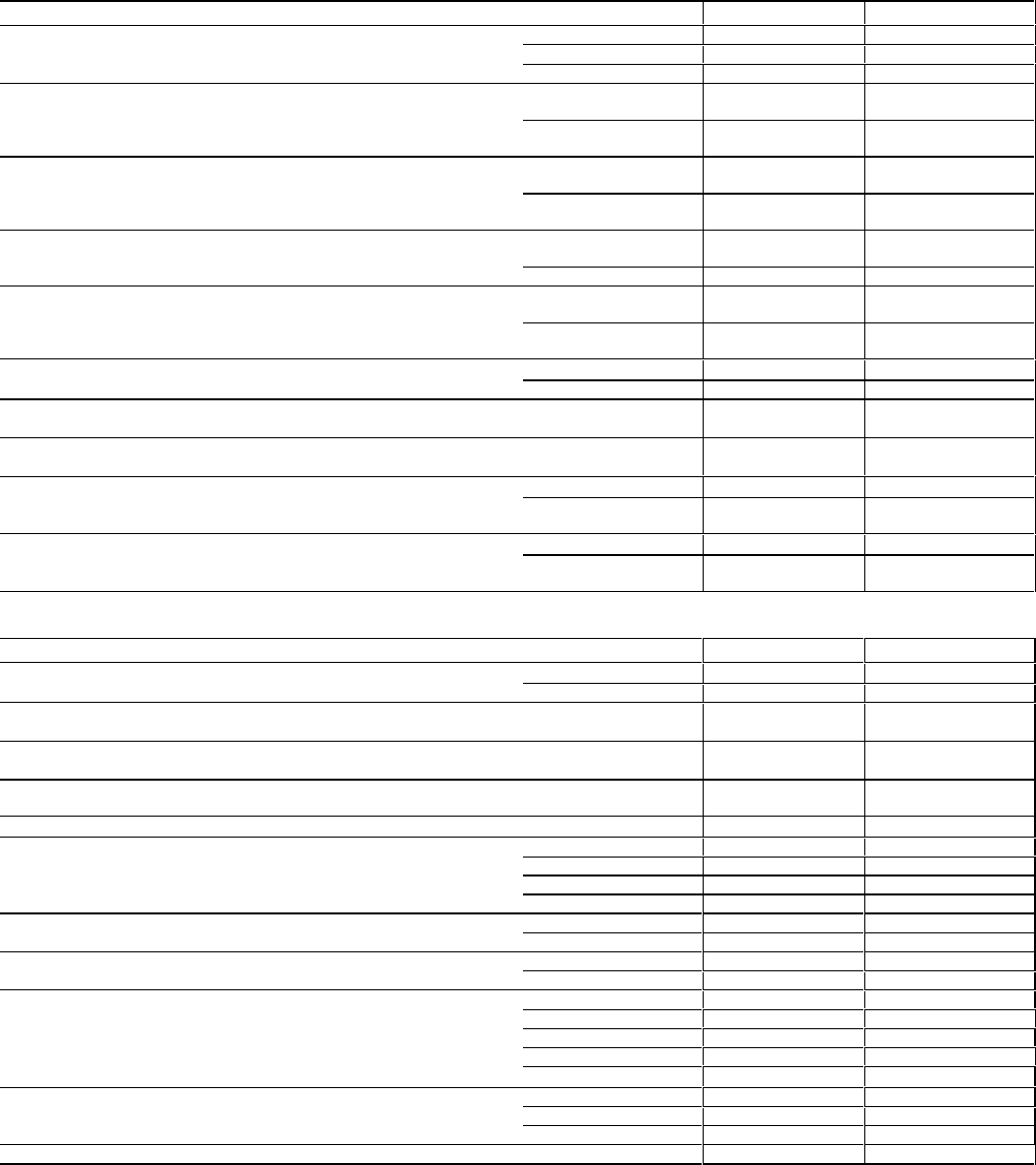
Table 1-1. Performance Specifications
Agilent Technologies Model 6033A 6038A
DC Output: Voltage, current and power spans indicate range Volts 0-20 V 0-60 V
over output may be varied using front panel controls.
Amps 0-30 A 0-10 A
Maximum Power 200-240 W 200-240 W
Load Effect (Load Regulation) Voltage load effect is given for a load
current change equal to the current rating of the supply. Current load
Voltage 0.01% + 2 mV 0.01% + 3 mV
effect is given for a load voltage change equal to the voltage rating of the
supply.
Current 0.01% + 9 mA 0.01% + 5 mA
Source Effect (Line Regulation): Given for a change within the rated line
voltage for any output within the rated output voltage, current and
Voltage 0.01% + 1 mV 0.01% + 2 mV
power of the supply Current 0.01% + 6 mA 0.01% + 2 mA
PARD (Ripple and Noise): Measured at any line voltage and under any
load condition within rating (rms 10 Hz to 10 Mhz/p-p 10 Hz to
Voltage 3 mV/30 mV 3 mV/30 mV
20 MHz) Current 30 mA/
1
5 mA/
1
Load Effect Transient Recovery: Maximum time required for output
voltage to recover with the specified band around the nominal output
Time 1 ms 1 ms
voltage following a 10% step change in output current while operating in
the constant voltage mode
Level 50 mV 75 mV
Programming: (25 ± 5°C) Given for control of the
Voltage Accuracy 0.035% + 9 mV 0.035% + 40 mV
output over the GP-IB or with front panel controls Current Accuracy 0.15% +20 mA 0.085% + 10 mA
Remote Voltmeter: (25 ± 5°C) Refers to data read back to the controller
over the GP-IB
Accuracy 0.07% + 6 mV 0.07% + 50 mV
Remote Ammeter: (25 ± 5°C) Refers to data read back to the controller
over the GP-IB.
Accuracy 0.3% + 25 mA 0.2% + 11 mA
Front Panel Voltmeter: (25 ± 5°C)
Range 2 V, 20 V, 200 V 2 V, 20 V, 200 V
Accuracy 0.07% +6 mV, 11
mV, 56 mV
0.07% + 50 mV, 55
mV, 100 mV)
Front Panel Ammeter: (25 ± 5°C)
Range 20 A, 200 A 20 A
Accuracy 0.3% + (20 mA, 65
mA)
0.2% + 11 mA
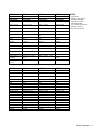
Table 1-2. Supplemental Characteristics
Agilent Technologies Model 6033A 6038A
Programming: (25 ± 5°C) Given for control of the
Voltage Resolution 5 mV 15 mV
output over the GP-IB or with front panel controls Current Resolution 7.5 mA 2.5 mA
Remote Voltmeter: (25 ± 5°C) Refers to data read back to the controller
over the GP-IB
Resolution 5 mV 15 mV
Remote Ammeter: (25 ± 5°C) Refers to data read back to the controller
over the GP-IB.
Resolution 7.5 mA 2.5 mA
Front Panel Voltmeter: (25 ± 5°C)
Resolution 5 mV, 10 mV, 100
mV
15 mV, 15 mV, 100
mV
Front Panel Ammeter: (25 ± 5°C)
Resolution 10 mA, 100 mA 10 mA
Maximum AC Input Current: +6% -13% (48-63) Hz
100 Vac (Opt.100) 6.0 A 6.0 A
120 Vac (Std.) 6.5 A 6.5 A
220 Vac (Opt.220) 3.8 A 3.8 A
240 Vac (Opt.240) 3.6 A 3.6 A
Temperature Coefficient: Output change per degree Celsius change
Voltage 50 ppm + 0.6 mV 50 ppm + 3 mV
in ambient following 30 minute warm-up. Current 100 ppm + 2 mA 90 ppm + 0.3 mA
Drift (Stability): Change in output (dc to 20 Hz) over 8-hour internal
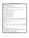
Voltage 0.02 % + 1 mV 0.02% + 2 mV
under constant line, load, and ambient following 30-minute warm-up Current 0.03% + 10 mA 0.03% + 3 mA
Programming Response Time: The maximum time required
Settling Band 5 mV 15 mV
to change from zero volts to full scale voltage or from full Up Full Load 100 ms 150 ms
scale voltage to 2 volts ( 5 volts for Agilent 6035A) and settle No Load 100 ms 120 ms
within the specified band. Full load is defined as the Down Full Load 200 ms 150 ms
resistance equal to Vp1/Ip1. Light load is as specified Light Load
500 ms (50 Ω) 750 ms (400 Ω)
Overvoltage Protection: Trip voltage adjustable via front
Range 0-23 V 0-63 V
panel control using the Display OVP function Resolution 100 mV 100 mV
Accuracy 0.3% + 200 mV 0.25% + 300 mV
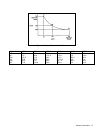
Typical input power at rated output power: (see point P
2
on Figure 1-1)
340 W 325 W


