MODENA 80 E
18
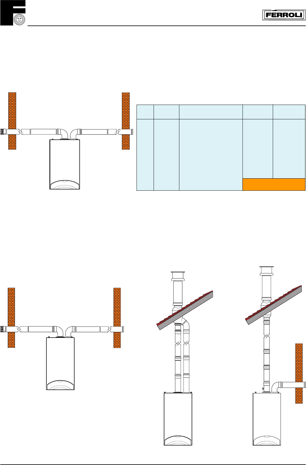
Example of wall inlet/outlet
Example of roof inlet/outlet
Example of direct roof flue outlet
and wall air inlet
3.04.3 Example of installation with two pipe systems
Fig. 25
Fig. 26 Fig. 27
For further accessories please refer to:
"Flue system manual for room sealed boiler"
Attention: flow resistance (reduction) equivalent included
between 38 and 48 (see table on page 27)
Remove the flue diaphragm.
The flue and air pipes must have an inclination downward
equal to 3%.
Example of calculation for wall inlet/outlet
with 2 pipe system
maximum total flue length: 48 metres
Fig. 24
REF. N
°
OF PIECES DESCRIPTION CODE LENGTH OR
REDUCTION
1 1 Air bend 80 mm R/D = 0,75 1,5 m
2 12 Horizontal air pipe 12,0 m
3 1 Air wall terminal 2,0 m
4 1 Air inlet closing flange —
5 1 Flue bend 80 mm R/D = 0,75 2,5 m
6 12 Horizontal flue 24,0 m
7 1 Air wall terminal outlet flue 5,0 m
TOTAL
47,0 m


