MODENA 80 E
15
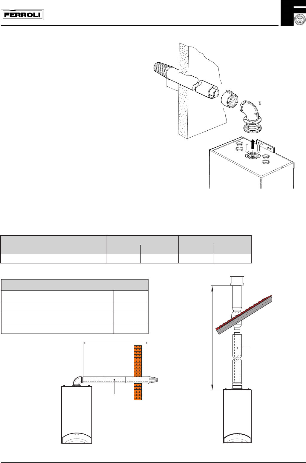
Fig. 21
Notes on concentric horizontal installation
To locate the centre of the hole for passing the
pipes through the wall, refer to fig. 15. Bear in
mind that the two concentric pipes must slope
downwards away from the boiler at a rate of
about 3 mm/m to avoid rainwater entering the
boiler. The concentric pipes making up the air -
flue gas duct must be sealed with the gasket
where they join the boiler (fig. 21). Outside, the
pipes should protrude from the wall between 10
and 60 mm (fig. 21).
Between
10-60mm
3.03.3 Maximum concentric flue length
First table below shows the maximum flue lengths available for boilers with concentric systems.
For correct calculation remember to include the reduction for bend and flue terminals listed on second table. Please
refer to 3.06 for use of restrictor
elbissimrepthgneleulfmumixaM
cirtnecnocmm001 cirtnecnocmm521
lacitreV *latnoziroH lacitreV *latnoziroH
E08animoDm4m3m5m5
slanimretfoordnadnebrofnoitcudeR
°09dnebcirtnecnocmm001m1
°54dnebcirtnecnocmm001m5,0
°09dnebcirtnecnocmm521m5,0
°54dnebcirtnecnoc521m52,0
*For horizontal Flueing the reduction for appliance bend or turret are already included.
max. 3 m
concentric
100/60
max. 4 m
concentric
100/60
Fig. 22a
Fig. 22b


