EPSON FX-2180 Service Manual Chapter 4 Disassembly and Assembly
4-22
Adjust the platen gap/parallelism and
bidirectional print alignment, and reset
the TPE level. (See Chapter 5.)
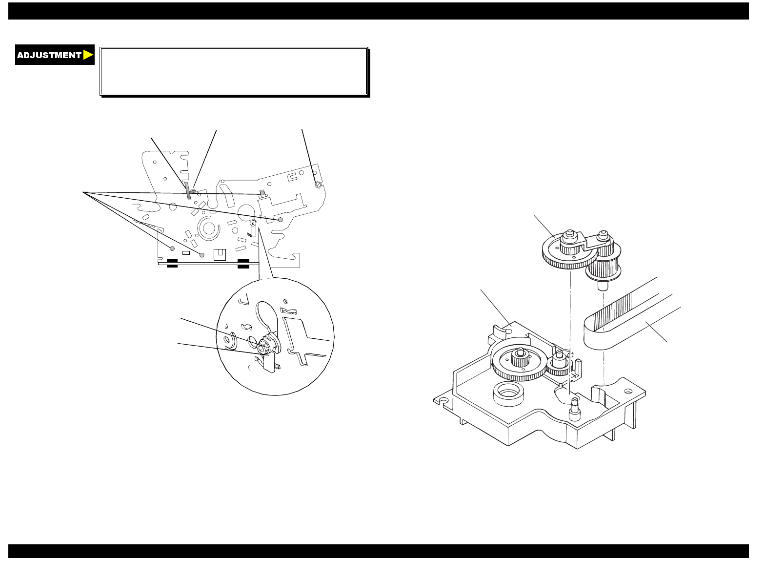
CBS screws (3 × 6)
securin
the left frame
hexa
onal nut (M4)
platen cover
CBS screw (3 × 6)
parallelism adjustment bushin
hexa
onal nut
Figure 4-30. Removing the Left Frame Assembly
4.2.11.8 Removing the Ribbon Drive (RD) Assembly
1.
Remove the printer cover, front and rear edge guide assemblies, front
cover, paper eject assembly, and front and rear tractor units. (See
section 4.2.1.)
2.
Remove the panel board assembly. (See section 4.2.2.)
3.
Remove the upper housing assembly. (See section 4.2.7.)
4.
Remove the printer mechanism. (See section 4.2.11.)
5.
Remove the CR motor tension spring and disengage the timing belt
from the CR motor pinion gear. (See section 4.2.11.1.)
6.
Remove the left frame assembly. (See section 4.2.11.7.)
7.
Remove the two CBS screws (3
×
8) securing the RD assembly to the
front frame.
8.
Remove the RD assembly from the front frame.
9.
Remove the timing belt from the RD assembly.
driven pulley assem bly
RD assembly
tim ing belt
Figure 4-31. Removing the RD Assembly


