


2 - 16
SPEC
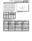
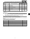
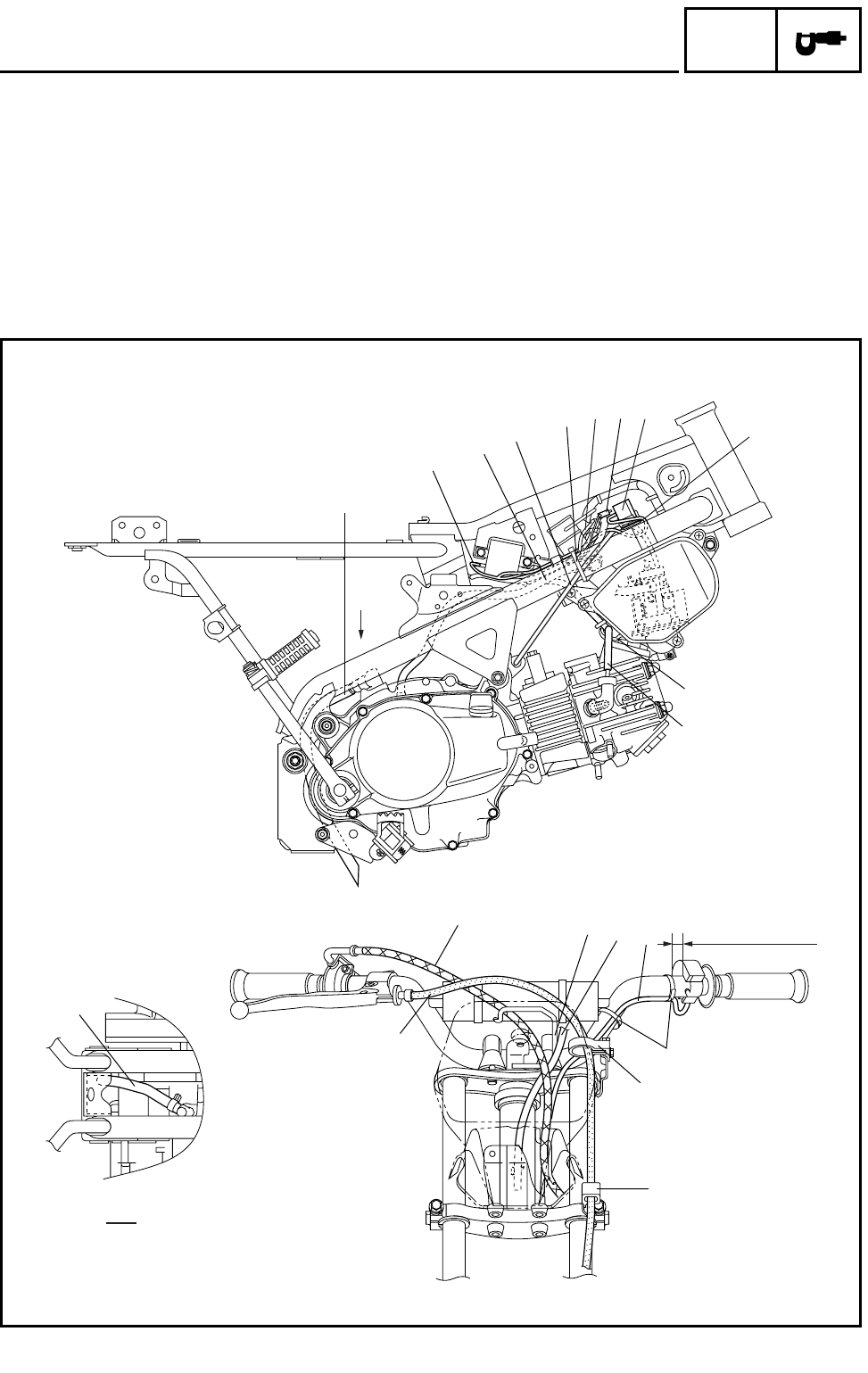
CABLE ROUTING DIAGRAM
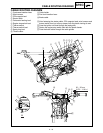
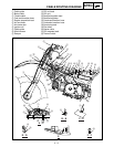
CABLE ROUTING DIAGRAM
1 Crankcase breather hose
2 Wire harness
3 CDI magneto lead
4 Starter cable
5 Carburetor heating lead
6 Engine stop switch lead
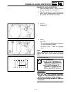
7 Thermo switch
8 Thermo switch lead
9 Spark plug lead
0 Throttle cable
A Cable holder
B Fuel tank breather hose
C Brake cable
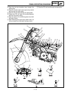
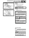
Å After fastening the starter cable, CDI magneto lead, wire harness and
thermo switch lead, cut off any excess from the plastic locking tie end.
ı Pass the ignition coil lead through the lead guide.
Ç Fasten the engine stop switch lead with the plastic bands.
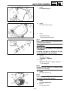
Î Pass the brake cable through the cable guides.
1
2
3
4
5
9
0
B
A
6
C
1
Å
ı
Ç
Î
Î
A
A
6
7
8
20 ~ 30 mm
(0.79 ~ 1.18 in)