


4
Start-up
Procedure
Installation of New Units
1. Follow all instruction for
installation of water source
heat pumps as detailed in the
IOM (Installation Operation
Maintenance manual).
2. Disconnect power or disable
the circuit breaker to unit.
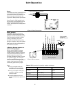
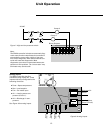
3. Run communication link wire to
field terminal strips 14 and 16.
(See wiring diagram in the
unit).
4. Install zone sensor to low
voltage control terminals 1
through 6. (See wiring diagram
in the unit and zone sensor
submittals).
5. Verify that water connections
have been made to unit, then
ensure that water is circulating
through the unit.
6. Reapply power.
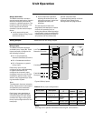
7. Check for STATUS GREEN LED
operation to ensure power and
communication has been made
to the ZN510
™
.
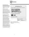
Peel IDENTIFICATION TAG from unit
and place in the ZN510 IOP, on a
copy of Sheet 6 of this document, or
on building plans for future location
use. The actual room location on the
tag may be hand written.
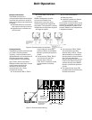
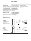
Zone Sensor Placement
Zone sensor location is an important
element of effective room control
and comfort.
The best sensor location is typically
on a wall, remote from the
HVAC unit.
Readings at this location assure that
the desired setpoint is achieved
across the space, not just near the
unit itself. It may be necessary to
subdivide the zone with multiple
units to ensure adequate control
and comfort.
The following are typical areas
where the zone sensor should not
be mounted:
z Near drafts or “dead spots”
(e.g., behind doors or corners)
z Near hot or cold air ducts
z Near radiant heat (e.g., heat
emitted from appliances or the
sun)
z Near concealed pipes or
chimneys
z On outside walls or other non-
conditioned surfaces
z In air flows from adjacent zones
or other units