


16
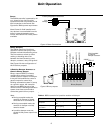
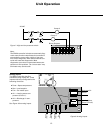
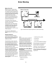
Zone Sensor
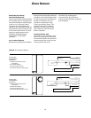
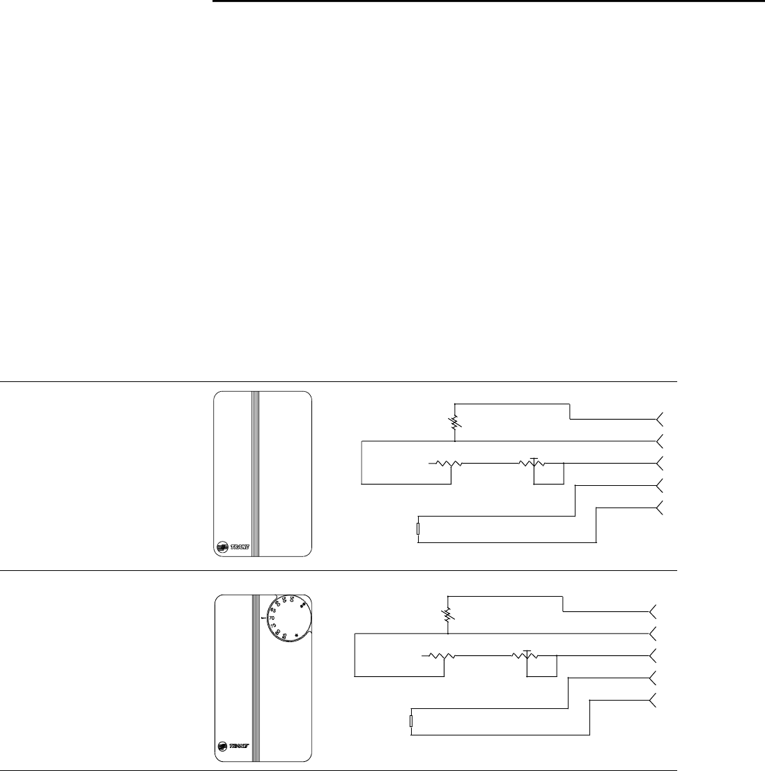
Table 6: Zone Sensor Options
Part Number:
X13510628010
Description:
z Space temperature (0.2 C
resolution).
z Internal setpoint.
z Communication jack.
z Vertical case with Trane logo
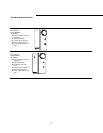
Part Number:
X13510606010
Description:
z Space temperature (0.2 C
resolution).
z External setpoint.
z Communication jack.
z Vertical case with Trane logo
5
4
3
2
1
ADJUSTABLE
SETPOINT
R7 1K
RT1
10K OHM @
25 °C ± 2°C
VR1
200
ZONE
SIGNAL (COMMON)
CSP
COMM HIGH (+ )
COMMUNICATIONS
JACK
MJ1
COMM LOW (-)
5
4
3
2
1
ADJUSTABLE
SETPOINT
R7 1K
RT1
10K OHM @
25 °C ± 2°C
VR1
200
ZONE
SIGNAL (COMMON)
CSP
COMM HIGH (+ )
COMMUNICATIONS
JACK
MJ1
COMM LOW (-)
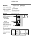
Zone Sensor Features
Fan Switch (Optional)
The zone sensor fan switch provides
the controller with an occupied (and
occupied standby) fan request signal
of
OFF or AUTO. If the fan control
request is communicated to the
controller, the controller ignores the
hardwired fan switch input and uses
the communicated value. The zone
sensor fan switch signal can be
enabled or disabled through
configuration in the ZN510
controller.
ON or CANCEL Buttons
Momentarily pressing the ON button
during unoccupied mode places the
controller in occupied bypass mode
for 120 minutes. You can adjust the
number of minutes in the unit
controller configuration using
Trane’s service tool, Rover. The
controller remains in occupied
standby mode until the override
timer expires or until the
CANCEL
button is pressed.
Communication Jack
Use the RJ-11 communication jack
as the connection point from Rover
to the communication link (when the
communication jack is wired to the
communication link at the
controller). By accessing the
communication jack via Rover,
entrance to all controllers on the link
may be gained.