


28
Diagnostics
Translating Multiple
Diagnostics
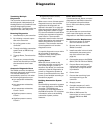
The controller senses and records
each diagnostic independently of
the diagnostics. It is possible to have
multiple diagnostics present
simultaneously. The diagnostics are
reported in the order they occur.
Resetting Diagnostics
1. Automatically by the controller.
2. By initiating a manual output
test at the controller.
3. By cycling power to the
controller.
4. Through a building automation
system such as ZN510 Loop
Controller.
5. Through Rover, Trane’s service
tool.
6. Through any communicating
device with the ability to access
the controller’s alarm reset
input.
Automatic Diagnostic Reset
The ZN510 controller includes an
automatic diagnostic reset function.
This function attempts to
automatically recover a unit when
the following diagnostics occur:
z Low temperature detection,
Circuit 1
z Low temperature detection,
Circuit 2
z Low temperature detection,
Circuit 1 and 2
z High/low pressure cutout,
Circuit 1
z High/low pressure cutout,
Circuit 2
z High/low pressure cutout,
Circuit 1 and 2
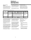
When one or more of these special
diagnostics occurs, the controller
responds to the diagnostic as
defined in the table 17 on page 27.
After the controller detects the first
special diagnostic (listed on page
27), the unit waits 30 minutes before
invoking the automatic diagnostic
reset function. The automatic
diagnostic reset function clears all
special diagnostics and attempts to
restore the controller to normal
operation. The controller resumes
normal operation until another
diagnostic occurs.
If a special diagnostic occurs within
24 hours after an automatic
diagnostic reset, the diagnostic
must be manually reset.
Cycling Power
When the 24
VAC power to the
controller has been turned off, the
unit cycles through a power up
sequence. By default, the controller
attempts to reset all diagnostics at
power up. Diagnostics present at
power up and those that occur after
power up are handled according to
the table on page 27.
Building Automation System
(CLC)
Some building automation systems
can reset diagnostics in the ZN510
controller. The ZN510 Loop
Controller can reset diagnostics in
the ZN510 Controller. For complete
information, refer to the building
automation system product
literature.
Rover Service Tool
Trane’s service tool, Rover, can reset
diagnostics in the ZN510 controller.
For complete information about
Rover, refer to the Rover product
literature.
Alarm Reset
Any device that can communicate
alarm reset information can reset
diagnostics in the ZN510 controller.
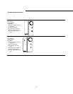
ZN510 Controller Replacement
1. Disconnect power or disable
the circuit breaker to unit.
2. Remove bad or questionable
ZN510 Controller.
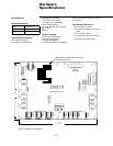
3. Install controller in the unit with
the heatsink placement at the
top of the control box. (See
page 32).
4. Connect the power to the ZN510
ONLY. (TB1-1 & TB1-2 on ZN510)
5. Connect Rover and properly
configure the controller, unless
a previously configured board
is purchased.
6. Power down.
7. Connect the remaining input
and output wiring to the
controller.
8. Reapply power.
9. Complete sequence 7 and 8
above in the installation section
of this manual.
10. Refer to BAS manual for
instructions on how to install
the new ZN510 into BAS
system.