


CNT-SVX07C-EN 63
Chapter 7
Troubleshooting
Use Table 17 through Table 22 to assist you in diagnosing any of the fol-
lowing operational problems that you might encounter with the Tracer
ZN521 zone controller:
• Fan does not energize (Table 17)
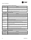
• Valves remain closed (Table 18 on page 64)
• Valves remain open (Table 19 on page 65)
• Compressors are not running (Table 20 on page 65)
• Electric heat does not energize (Table 20 on page 65)
• An outdoor air damper stays closed (Table 21 on page 66)
• An outdoor air damper stays open (Table 22 on page 66)
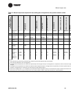
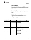
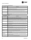
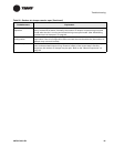
Table 17. Fan does not energize
Probable cause Explanation
Unit wiring The wiring between the controller outputs and the fan relays and contacts must be
present and correct for normal fan operation. Refer to applicable wiring diagram.
Failed end device The fan motor and relay must be checked to ensure proper operation.
Normal operation The fan will turn off when the controller receives a communicated off signal, when the
fan-speed switch is set to OFF, when specific diagnostics are generated, or when the
default fan speed is set to Off and the fan is operating in the Auto mode. If the controller
is in unoccupied mode, the fan cycles between off and the highest fan speed.
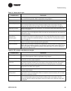
No power to the con-
troller
If the controller does not have power, the unit fan does not operate. For the Tracer ZN521
controller to operate normally, it must have an input voltage of 24 Vac. If the green LED is
off continuously, the controller does not have sufficient power or has failed.
Power-up control-wait If power-up control-wait is enabled (non-zero time), the controller remains off until one of
two conditions occurs:
1) The controller exits power-up control-wait after it receives communicated information.
2) The controller exits power-up control-wait after the power-up control-wait time expires.
Diagnostic present Several diagnostics affect fan operation. For information about these diagnostics, see
Table 16 on page 59.
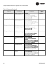
Unit configuration The controller must be properly configured based on the actual installed end devices and
application. If the unit configuration does not match the actual end device, the fans may
not work correctly.
Manual output test The controller includes a manual output test sequence you can use to verify output oper-
ation and associated output wiring. However, based on the current step in the test
sequence, the unit fan may not be on. Refer to the “Manual output test” on page 52.
Random start
observed
After power-up, the controller always observes a random start from 5 to 30 seconds. The
controller remains off until the random start time expires.