


Interpreting LEDs
CNT-SVX07C-EN 57
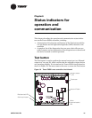
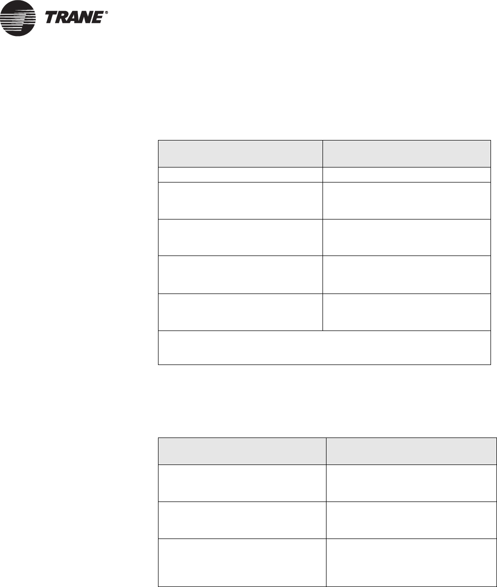
The green (status) LED on the Tracer ZN521 controller (see Figure 19 on
page 51) indicates whether the controller has power applied to it and if
the controller is in manual test mode (see Table 14).
The yellow (communications) LED on the Tracer ZN521 controller (see
Figure 19 on page 51) indicate the controller’s communication status (see
Table 15).
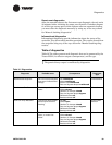
Table 14. Green LED: Status indicator
LED activity Explanation
LED is on continuously. Power is on (normal operation).
LED blinks (one recurring blink). Manual output test mode is being
performed and no diagnostics are
present.
LED blinks (blinks twice as a recur-
ring sequence).
Manual output test mode is being
performed and one or more diag-
nostics are present.
LED blinks (1/4 second on,
1/4 second off for 10 seconds).
The Auto-wink option is activated,
and the controller is
communicating.
1
LED is off continuously. Either the power is off,
the controller has malfunctioned, or
the Test button is being pressed.
1
By sending a request from the Rover service tool, you can request the controller’s
green LED to blink (“wink”), a notification that the controller received the signal
and is communicating.
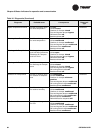
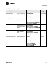
Table 15. Yellow LED: Communications indicator
LED activity Explanation
LED is off continuously The controller is not detecting any
communication (normal for stand-
alone applications).
LED blinks. The controller detects communica-
tion (normal for communicating
applications, including data sharing).
LED is on continuously. Problem with communication link
wiring (possible need for termination
resistor), or controller failure (caused
by power surge, lightning strike, etc.)