


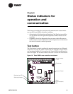
Chapter 6 Status indicators for operation and communication
54 CNT-SVX07C-EN
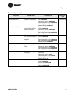
11: Exit
5
1
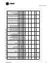
The controller turns off all fan and electric heat outputs and drives all dampers and valves closed.
2
The controller attempts to clear all diagnostics.
3
If configured for a 3-speed fan, the medium fan speed output will energize at step 3. If configured for a 2-speed fan, the fan remains on high speed at
step 3.
4
If configured for a 3-speed fan, the medium fan speed output energizes at step 4. If configured for a 2-speed fan, the low fan speed output energizes at
step 4. If configured for a 1-speed fan, the fan remains on high speed at step 4.
5
If the unit is configured for a 1- or 2-speed fan, the exhaust fan output energizes on step 7. The exhaust fan output is shared with medium fan speed.
6
After step 10, the manual output test performs an exit, which initiates a reset to restore the controller to normal operation.
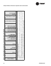
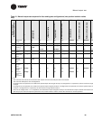
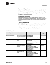
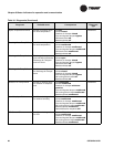
Table 11. Manual output test sequence for non-face-and-bypass configurations
Step Result BOP1 BOP2 BOP3 BOP4 BOP5 BOP6 BOP7 BOP8 BOP9 BOP10
Number of times
Test button is pressed
Fan high
1)Fan medium
2)Exhaust
Fan low
1)Cooling/changeover
valve, open
2)Two-position cooling/
changeover valve
3)DX compressor
Cooling/changeover
valve, close
1)Heating valve, open
2)Two-position heat valve
3)Electric heat, stage 1
1)Heating valve, close
2)Electric heat, stage 2
Outdoor air damper, open
Outdoor air damper, close
1)Generic
2)Baseboard heat