1-24 (E)
HDCU-950 IMM
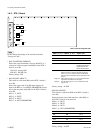
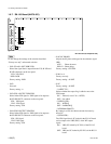
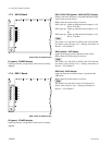
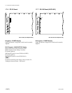
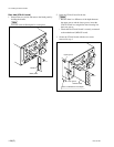
1-7-3. AVP-4 Board
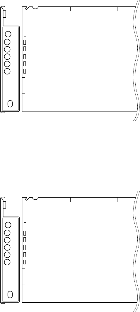
AVP-4 board (A side/panel side)
D1 (green) : POWER display
Lights up when the voltage used on this board is normally
supplied.
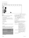
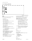
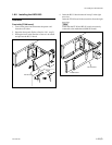
1-7-4. DRX-1 Board
DRX-1 board (A side/panel side)
D2 (green) : POWER display
Lights up when the voltage used on this board is normally
supplied.
AB C D E
1
2
3
4
5
D205
D204
D203
D202
D201
D2
DRX
POWER
CHARACTER
60
50
48
540P
REW
FF
PsF
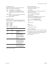
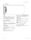
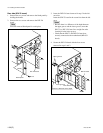
D201, D202, D203 (green) : MAIN OUTPUT display
Displays the frame frequency of the MAIN HD SDI output
signal of this unit and camera.
Blinks when the format setting is incorrect.
D201 lights up : Lights up when the frame frequency is 30
Hz (or 29.97 Hz)
D202 lights up : Lights up when the frame frequency is 25
Hz.
D203 lights up : Lights up when the frame frequency is 24
Hz (or 23.98 Hz)
n
The format is set with S418 to S420 on the AT-149 board.
For details, refer to Section 1-6-1. “Setting of Switches on
Boards _ AT-149 Board”.
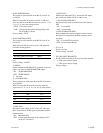
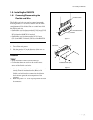
D204 (yellow) : PsF display
Lights up during progressive operation of the camera.
Blinks when the format setting is incorrect.
n
The format is set with S418 to S420 on the AT-149 board.
For details, refer to Section 1-6-1. “Setting of Switches on
Boards _ AT-149 Board”.
D205 (red) : 540P display
Lights up when the connected camera is operated in the
540P mode.
Blinks when the format setting is incorrect.
n
The format is set with S419 on the AT-149 board. For
details, refer to Section 1-6-1. “Setting of Switches on
Boards _ AT-149 Board”.
AB C D E
1
2
3
4
5
D205
D204
D203
D202
D201
D2
DRX
POWER
CHARACTER
60
50
48
540P
REW
FF
PsF
1-7. Functions of Indicators on Boards


