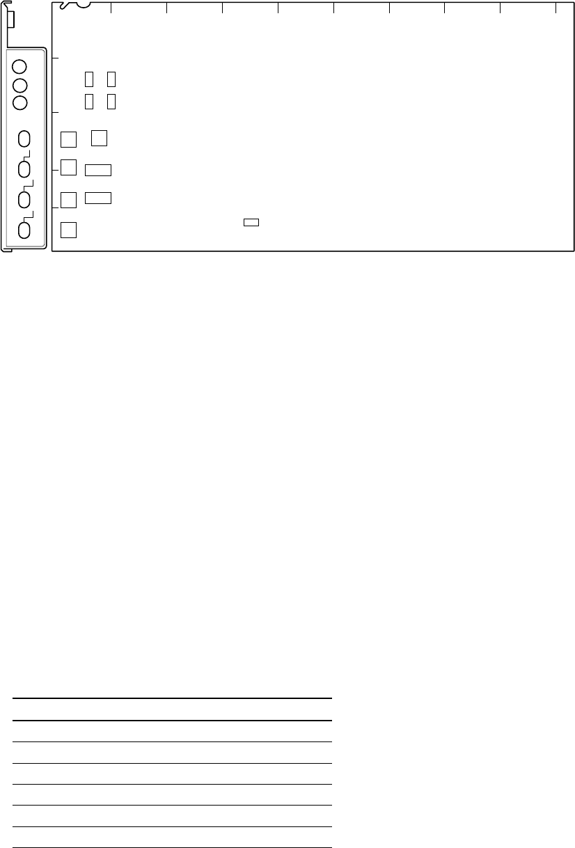
1-18 (E)
HDCU-950 IMM
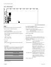
AB C D E F G H JK
1
2
3
4
5
S10
S11
S3S1
S4 S2
S5
S301
S6
S7
S8
S9
RC
POWER
525
625
REM
LOCAL
SQ
LB
EC
CENT
VAR
RIGHT
LEFT
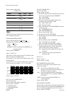
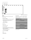
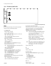
RC-91 board (A side/panel side)
1-6. Setting of Switches on Boards
1-6-6. RC-91 Board
n
Do not change the settings of the switches described
“Factory use only” and unused switches.
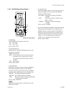
. S1 (SET-UP ON/OFF)
Selects whether SETUP is added or not to the VBS
signal to be output from PIX OUT/WF OUT connector
on the rear panel.
ON : Added
OFF : Not added
Factory setting : OFF
. S2, S3, S4
Not used.
Factory setting :Left side when viewed from the panel
side.
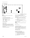
. S5 (CB-SEL)
Selects the color bar signal to be output from the SD SDI
OUT 1 and 2 connectors and the VBS OUT connector
(when the HKCU-951 is installed) on the rear panel.
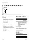
Setting switches Color bar
0 100%-CB (non-split)
1 100% & 75%-CB (non-split)
2 75%-CB (non-split)
3 Pseudo SMPTE-CB
4 Mode to down-convert HD-CB
5-F Not used
Factory setting : 0
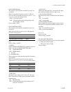
. S6 (ASPECT REMOTE/LOCAL)
Sets whether RCP/MSU connected outside controls or
not the aspect ratio of the SD signal.
REM : Control is performed by RCP/MSU, etc.
connected outside.
LOCAL :Set using the switch on the RC-91 board.
Factory setting : REM
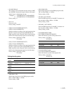
. S7 (ASPECT SEL)
This switch is valid when S6 on the RC-91 board is set
to LOCAL. Selects the aspect ratio to down-convert the
HD signal to SD signal.
SQ (Squeeze) : The HD video signal of 16 : 9 is
output to the SD OUT.
LB (Letter Box) : The picture (13 : 9, 14 : 9, 15 : 9 or
16 : 9) having the aspect ratio
selected by S10-3 and S10-4 on the
RC-91 board is inserted in the
picture of 4 : 3 as it is, and the signal
is output to the SD OUT.
(Top and bottom are blanked and the
right and left most ends are cut when
the screen is 13 : 9, 14 : 9 or 15 : 9.)
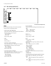
EC (Edge-Crop) : The right and left most ends are cut
and the picture of 4 : 3 aspect ratio is
output to the SD OUT. (Set the
cutting position using S8 on the RC-
91 board.)
Factory setting : SQ


