


1-9 (E)
HDCU-950 IMM
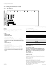
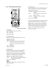
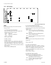
1-6. Setting of Switches on Boards
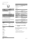
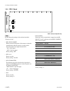
S411
S413
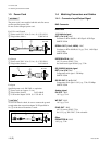
. S408 (MARKER REMOTE/LOCAL SEL)
Selects either the HDCU-950 or the RCP/MSU connect-
ed outside in order to control the aspect marker and skin
gate signal to be inserted in the HD SDI MONITOR
output signal and in the PIX output signal that are output
from the MONI connector on the rear panel.
REM :Control is performed by RCP/MSU etc., con-
nected outside.
LOC : Control is performed by the switches (S402,
S403, S409 and S410) on the AT-149 board.
Factory setting : REM
. S409 (MARKER)
When S408 on the AT-149 board is set to LOC, this
switch enables selection whether the ASPECT MARK-
ER signal is inserted or not in the HD SDI MONITOR
output signal and in the PIX output signal that are output
from the MONI connector on the rear panel.
ON : Inserted
OFF : Not inserted
Factory setting : OFF
. S410 (MODULAT)
When S408 on the AT-149 board is set to LOC, this
switch enables selection whether the HD SDI MONI-
TOR output signal that is output from the MONI connec-
tor on the rear panel, receives the aspect modulation
processing or not.
ON : Processing is ON
OFF : Processing is OFF
Factory setting : OFF
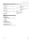
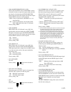
. S411 (RCP-PORT)
Not used.
Factory setting : ( indicates the switch lever
position)
. S412 (SYNC OUT HD/SD)
Selects the type of the SYNC signal to be output from
the SYNC OUT connector on the rear panel.
HD : HD SYNC signal output
SD : SD SYNC signal output
Factory setting : SD
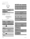
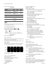
. S413
Not used.
Factory setting : ( indicates the switch lever
position)
. S414 (FIBER/COAX-1/COAX-2 SEL)
When S423-8 on the AT-149 board is set to ON, select
the camera signal reception mode of the HDCU-950.
When S423-8 on the AT-149 board is set to OFF
(factory setting), the signal is connected by the normal
optical/electrical composite cable.
FIBER : Connection by normal optical/electrical
composite cable
COAX-1 :One-way connection using a BNC cable
*1
COAX-2 :Bi-directional connection using two BNC
cables
*2
Factory setting : FIBER
*1: After receiving the HD-SDI signal output from the camera, the signal
is locked and each signal is output correctly. (RET3 connector is
used for the HD-SDI signal input connector from the camera.)
*2: Connecting the camera equipped with the HD-SDI input/output is
possible using the two BNC cables instead of the optical/electrical
composite cable. Then the normal operation is possible except the
power feeding function. (As to the HD-SDI output signal to the
camera, the output signal from HD SDI MONITOR is used.)
However, this function cannot be used by default at present. If you
want to use this function, consult your local Sony Sales Office/
Service Center.
. S416 (REF-10F-BB) (NTSC only)
Sets this switch when the multi frame is going to be
locked using the 10F-BB signal (SMPTE318M) as a
reference signal.
ON : Sets the 10F-BB signal as reference.
OFF : When the 10F-BB signal is not input to REFER-
ENCE.
Factory setting : OFF
. S417 (CONVERSION DELAY)
Selects delay amount between the HD-SDI output signal
and the SDI signal after the HD-SDI signal is down-
converted.
90H : Minimum delay mode equivalent to 90H
lines of HD signal.
1FRAM : Unity phase mode with 1 frame delay
Factory setting : 90H
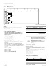
. S418 (FIELD FREQUENCY SEL)
. S419 (INTR/PROG/540P SEL)
When S420 on the AT-149 board is set to the position
other than REMOTE, sets the conversion format of the
MAIN HD SDI output signal that is output from the HD
SDI OUT1 and 2 connectors on the rear panel.
n
The MULTIFORMAT setting of the camera side shall
have the same setting too.