+
- 86 -
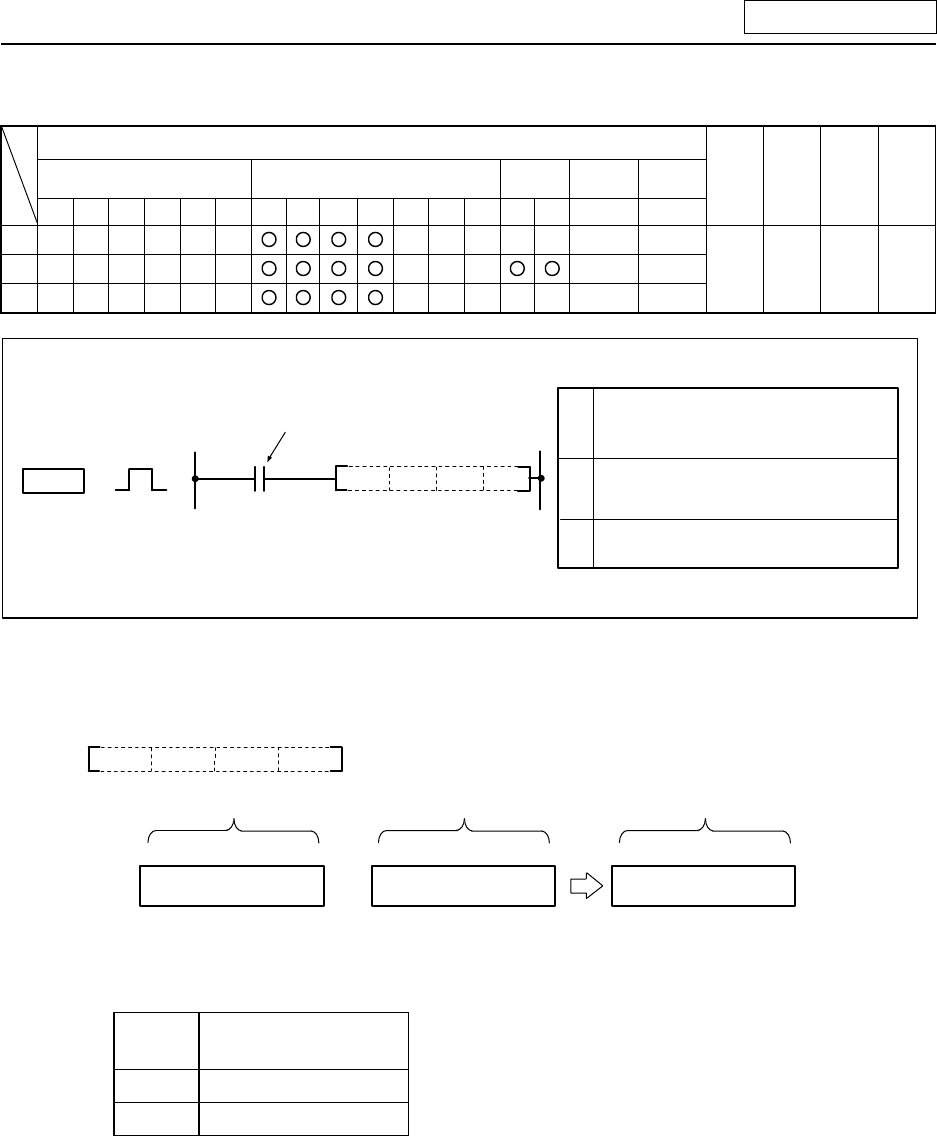
{+ ... BIN 16-bit addition
Usable device
Bit device Word device
Con-
stant
Pointer Level
X Y M L SM F T C D R Z K H P N
Digit
desig-
nation
No. of
steps
Index
S1
S2
D
4
Addition command
+
+ S2S1
D
Setting data
S2
S1
No. of device to store addition
results.
D
Addition data or No. of device
where addition data is stored.
Addition data or No. of device
where addition data is stored.
Function
(1) The BIN data designated with S1 and the BIN data designated with S2 are added, and the
addition results are stored in the device designated with D.
+ S2S1 D
5678 (BIN) 1234 (BIN) 6912 (BIN)
B15.....................B0
+
S1
S2 D
B15.....................B0
B15.....................B0
(2) -32768 to 32767 (BIN 16-bit) can be designated in S1 and S2.
(3) The positive/negative of the data in S1, S2 and D is determined with the highest-order bit (B15).
B15
Judgment of
positive/negative
0 Positive
1 Negative
(4) The carry flag will not turn ON even if an overflow results.


