


SIM4-02 HARDWARE SIMULATOR
1.0 INTRODUCTION
The
SIM4-02 Hardware
Simulator
is
a program
written
for
the
MCS-4 ™ series Micro
Computer
System. This program
will provide interactive
control
over
the
debugging
of
other
MCSA ™ programs.
The
minimum configuration requited
is
a
SI
M4-02
prototype
card
with
three
4002
RAMs and a Teletype. When fully
stuffed
with 16 RAMs,
test
programs
up
to
512 bytes (locations)
in
length may be accomodated.
The
hardware simulation program
itself occupies nine full ROMs.
The
Hardware Simulation Program has
two
basic functions:
1.
To
simulate
the
execution
of
a
test
program, tracing its progress, and apprehending gross errors.
2.
To
allow
the
user
to
dynamically interact with
and/or
modify
his
test
program,
in
order
to
facilitate
the
debugging
process.
These
two
functions
are implemented by means
of
a set
of
directives
or
commands
which
the
user
types
in
at
the
teletype
keyboard.
Some
of
the
directives call for
typeouts
by
the
simulator program,
some
of
the
directives signal
the
input
of
data
or
program modifications, and some
of
the
directives involve
both
typeouts
and
input
response
or
data.
A directive
is
identified
by
a single letter
of
the
alphabet
(except
the
arithmetic conversion directives = and It). If
the
directive
is
associated
with
output
only,
the
typing (or punching) will
commence
immediately. If
input
is
allowed
or
re-
quired with
the
directive,
the
simulation program will enable
the
paper
tape
reader
control,
and
wait
for valid
input
data.
2.0 NUMBER SYSTEMS
Two
number
radices are standard with
the
hardware simulation program: binary and decimal. Index register values, pro-
gram
counter
and
instruction location values, chip numbers, and some pointers are handled in decimal for convenience.
ROM
instructions,
the
accumulator
value, and one-bit indicators are handled
in
binary.
Any
input
number
may
be
entered
in
either radix
by
prefixing it with a suitable indentifier
("0"
for decimal,
"8"
for
binary), regardless
of
the
expectations
of
the
program. Unless so identified, however, all
input
should be
in
the
radix used
in
the
corresponding
typeout.
To
facilitate working
with
program tapes
in
the
"BNPF"
format,
the
hardware simulation program will
accept
binary
num-
bers coded either
as
strings
of
ones and zeroes,
or
as
strings
of
"P"s
and
"N"s,
where
the
letter
P
is
interpreted as a zero, and
the
letter N
is
interpreted as a one.
All
input
numbers
are right-justified into
the
receiving register
or
field.
If
the
number
is smaller
than
the
receiving field,
leading zeroes are implied as necessary. If
the
number
is
larger
than
the
receiving field,
the
excess bits are lost
from
the
most-
significant end of
the
number. Thus,
if
it
is
attempted
to
load
an
index register
with
the
value 20,
the
result will be 4
in
the
register. This may be used
to
advantage
in
the
event
of
an inadvertant error
typein,
by typing
in
as
many zeroes as
there
are
bits
in
the
receiving field,
then
re-typing
the
number, all as one string
of
digits. A
number
typed
in
may end
with
a carriage
return, a
comma,
a space,
or
the
letter
"F",
or
in
the
case
of
the
= directive, with plus
or
minus sign.
Any
other
characters
will give unpredictable results, and should be avoided.
Rubouts
are
the
only non
"numeric"
characters which
may
be imbed-
ded within
the
input
number
strings with no adverse effects.
Rubouts
are ignored
in
all cases.
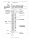
3.0 DESCRIPTION
The
hardware simulation program allocates a user-selected block
of
RAM
main
memory
locations
to
hold
the
ROM
instruc-
tions
to
be simulated, assigning
two
RAM
locations for each simulated
ROM
location.
Thus,
to
simulate
512
locations
of
ROM, all 16 RAMs
must
be used.
Any
RAM
locations
not
allocated for program storage
may
be accessed
in
the
normal
way
by
the
test
program.
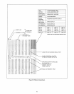
In
addition,
the
hardware simulation program uses
the
status
characters
in twelve consecutive
RAM
registers (equivalent
to
three
RAM
chips)
to
hold simulation parameters.
RAM
is
assumed
to
be organized as
four
consecu-
tive banks (with wraparound)
of
sixteen registers each, so
that
if less
than
16 RAMs are used,
those
allocated
to
program and
parameter storage
must
be in
one
block
of
contiguous
banks and registers within banks.
The
program
to
be tested may have an address anywhere in
the
4096
locations
of
addressable, ROM, since
the
hardware
simulator program adds a bias value
to
all addresses
which
reference
the
simulated ROM. If
the
program
attempts
to
jump
or
increment
to
outside
the
range
of
the
simulated ROM, an error
interrupt
occurs.
Another
error
interrupt
occurs
in
the
event
of
an illegal instruction
op
code
during simulated
execution.
The
op
codes
which
cause this
interrupt
are:
11111110,
11111111,
11100011,
and
all
instructions
with
aPR
=
0000
except
for
00000000
(NaP).