


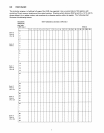
The bank number
in
the
chart above
is
the
value
of
the
accumulator during a
DCl
instruction, needed
to
address
that
bank
of
RAMs.
The
port
number given corresponds
to
the
number
typed
out
during simulation
of
the
WMP
instruction. Register
positions 16-19 (Le.,
the
status locations) are normally addressed
in
the
program by
the
RDO/WRO,
RD
1 /WR 1, etc.,
instructions, respectively.
The
Q directive
is
used
to
define and set aside some part
of
RAM
for use by
the
simulation program
as
simulated
ROM
and
other
registers and parameters. Whole
RAM
registers are taken by
the
Q directive, beginning with
the
register identified
in
the
first parameter.
The
status locations from exactly 12 registers are used
by
the
simulator. The number of main memory
locations used
is
determined
by
the
difference between
the
second and third parameters of
the
Q directive. Where
sand
e
represent
the
values
in
the
second and
third
parameters
of
the
Q directive,
the
number
of
registers used
is
determined by
the
formula: n =
(s
+ e}/8 + 1
This value may be more
or
less than 12,
the
number
of
registers whose
status
locations are used, with no
ill
effects.
RAM
main
memory
locations reserved by
the
Q directive are used solely for program storage.
The
instruction with an
address equal
to
the
second parameter
of
the
Q instruction
is
loaded into digits 0 and 1
of
the
register designated
by
the
first parameter
of
the
Q directive; subsequent instructions are loaded into
the
following digit pairs, according
to
the
addresses.
The
RAM
status
locations reserved by
the
simulation program are allocated
to
the
following functions:
Relative
REGISTER
lOC'N.
FUNCTIONS
r + 0
0
Simulated
Accumulator
0
1-3
low
ROM
address limit
0
Option
word
1
1-3
High
ROM
address limit
2
0
Execution parameters
2
1-3
Breakpoint address
3
0
Simulated Carry
3 1-3
Simulation
Cycle
counter
4
0
Simulated Stack
pointer
4-7
1-3
Simulated Stack
5
0 Simulated Command line selection
6,7
0 Simulated
ROM
or
RAM
chip selection
8-11
0-3
Simulated
index registers
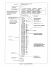
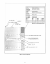
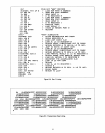
9.0 EXAMPLES
Figures 9.1,
9.2
and
9.3
are annotated listings generated during actual simulation. Figure 9.1
is
a simulation of
the
"ANO"
program described
in
figures
9.4
and 9.5. Figures
9.2
and 9.3 represent
the
simulator's response
to
various directives
entered
via
a
TTY
keyboard.
8