


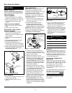
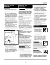
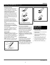

obtaining a satisfactory weld. Weld
angle involves two positions - travel
angle and work angle.
Travel angle is the angle in the line of
welding and may vary from 5º to 45º
from the vertical, depending on
welding conditions.
Work angle is the angle from hori-
zontal, measured at right angles to the
line of welding. For most applications, a
45º travel angle and 45º work angle is
sufficient. For specific applications,
consult an arc welding handbook.
8
Wire Feed Arc Welder
Welding Guidelines
(Continued)
WIRE SPEED
The wire speed is controlled by the
knob on the front panel. The speed
needs to be “tuned” to the rate at
which the wire is being melted in the
arc. Tuning is one of the most critical
functions in wire feed welding. Tuning
should be performed on a scrap piece
of metal the same type and thickness as
that to be welded. Begin welding with
one hand “dragging” the gun nozzle
across the scrap piece while adjusting
the wire speed with the other hand.
Too slow of speed will cause sputtering
and the wire will burn up into the
contact tip. Too fast a speed will also
cause a sputtering sound and the wire
will push into the plate before melting.
A smooth buzzing sound indicates the
wire speed is properly tuned. For
aluminum, wire speed is typically set
higher (7 - 9 speed range).
NOTE: Repeat the tuning procedure
each time there is a change in heat
setting, wire diameter or type, or work
piece material type or thickness.
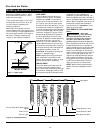
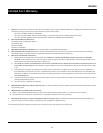
TRAVEL SPEED
The travel speed is the rate at which
the torch is moved across the weld
area. Factors such as diameter and type
of weld wire, amperage, position, and
work piece material thickness all affect
the speed of travel necessary for
completing a good weld (See Fig. 10).
When the speed is too fast, the bead is
narrow and bead ripples are pointed as
shown. When the speed is too slow, the
weld metal piles up and the bead is
high and wide. For aluminum, travel
speed is typically faster.
SLAG REMOVAL (FLUX-CORE WIRE
ONLY)
Wear ANSI
approved safety
glasses (ANSI Standard Z87.1) and
protective clothing when removing
slag. Hot, flying debris can cause
personal injury to anyone in the area.
After completing the weld, wait for the
welded sections to cool. A protective
coating called slag now covers the weld
bead which prevents contaminants in
the air from reacting with the molten
metal. Once the weld cools to the point
that it is no longer glowing red, the
slag can be removed. Removal is done
with a chipping hammer. Lightly tap
the slag with the hammer and break it
loose from the weld bead. The final
clean-up is done with a wire brush.
NOTE: When making multiple weld
passes, remove the slag before each
pass.
!
WARNING
TRAVEL ANGLE
WORK ANGLE
5º - 45º
5º - 45º
Figure 9 - Weld Angle
www.chpower.com
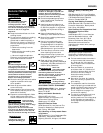
Normal Heat, Wire Speed, Travel
Speed
Heat Too Low
Heat Too High
Wire Speed Too Fast
Wire Speed Too Slow
Travel Speed Too Slow
Travel Speed Too Fast
Base Metal
Figure 10 - Weld Appearance