


5
WG3020
MODEL WT1000
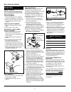
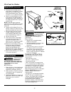
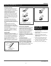
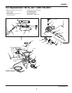
1. Remove the lens retainer from the
face shield with a regular screwdriver
by prying against the shield and post
of the lens retainer.
2. Remove the protective film covering
from both sides of each lens cover.
Put one clear lens cover on each side
of the shaded lens. Place these three
lenses together into the face shield
and secure with the lens retainer. The
lens retainer should snap into the
second notch in the face shield.
3. Position one of the holes in the
adjustment arm over the pins which
are located in the ear area of the face
shield. These adjustment arms control
the closeness of fit and can be easily
repositioned if necessary.
4. Position the headgear inside the face
shield. Assemble the helmet by
inserting the stud screw through the
headgear and shield into the tension
nut as shown. Do not tighten tension
nut completely.
5. Trial fit the welding helmet. Adjust
headgear ratchet band to a
comfortable position and lower the
face shield. If the shield is too far or
too close to the face, use a different
hole in the adjustment arm. Adjust
the tension nuts so that helmet can be
easily lowered over the face by
nodding the head.
Improper handling
and maintenance
of compressed gas cylinders and
regulators can result in serious injury
or death! Always secure gas cylinders
to the tank bracket kit, a wall or other
fixed support to prevent the cylinder
from falling over. Read, understand,
and follow all the compressed gases
and equipment hazards in the safety
instructions.
NOTE: Shielding gas is not required if
flux-cored welding wire is used.
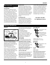
GAS TYPES
There are 3 types of gas generally used
for gas metal arc welding; 100% argon,
a mixture of 75% argon and 25%
carbon dioxide (C25) or 100% carbon
dioxide. The 75/25 mixture is
recommended for general steel
welding. For aluminum welding, use
100% argon. Cylinders of each type gas
may be obtained at your local welding
supply outlet. Secure cylinder in place
on your welding machine or other
support to prevent the cylinder from
falling over.
NOTE: Use of incorrect gas may lead to
little or no penetration of welding
bead.
REGULATOR
The regulator supplied with this unit
does not have any gauges. The regulator
provides a constant shielding gas
pressure and flow rate during the
welding process. Each regulator is
designed to be used with a specific gas or
mixture of gases. The argon and argon
mixture use the same thread type. The
100% carbon dioxide uses a different
thread type. An adapter is supplied with
the unit to change between the two.
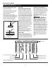
HOOKUP PROCEDURE
Cylinder gas is
under high
pressure. Point cylinder outlet away
from yourself and any bystanders
before opening.
1. This unit fits a 20 cubic ft bottle.
2. With the cylinder securely installed,
remove the cylinder cap, stand to the
side of the cylinder opposite the
outlet, and open the valve slightly,
turning counterclockwise. When gas
is emitted from the cylinder, close the
valve by turning clockwise. This will
blow out dust or dirt that may have
accumulated around the valve seat.
!
WARNING
!
DANGER
3. Install the regulator onto the
cylinder valve, keeping the face of
the gauges in the vertical position
(if applicable) and tighten the stem
nut securely to the gas valve.
4. Install one end of the gas hose to
the fitting on the rear of the welder
and the other end to the fitting on
the regulator using hose clamps on
each connection. Make sure the gas
hose is not kinked or twisted.
5. Once again, stand opposite the
cylinder outlet and slowly open the
cylinder valve. Inspect for leaks in
the connections.
6. Pull the trigger on the gun to allow
the gas to flow. While the trigger is
pulled and gas is flowing, adjust the
gas regulator turn regulator knob
clockwise for maximum gas flow.
Release the trigger.
7. Remember to close the gas valve
when finished welding.
1. Be sure to read,
understand, and comply
with all precautions in
the General Safety
Information section. Be
sure to read the entire section
entitled Welding Guidelines prior to
using this equipment.
2. Verify welder is off.
3. Verify that the surfaces of metals to
be joined are free from dirt, rust,
paint, oil, scale or other contam-
inants. These contaminants make
welding difficult and cause poor
welds.
All persons operating this
equipment or in the area
while equipment is in use
must wear protective welding gear
including: eye protection with proper
shade, flame resistant clothing, leather
welding gloves, and full foot
protection.
If heating, welding, or
cutting materials that are
galvanized, zinc plated, lead,
or cadmium plated refer to the General
Safety Information Section for
instructions. Extremely toxic fumes are
created when these metals are heated.
!
WARNING
!
DANGER
Figure 5
Headgear
Face Shield
Shaded Lens
Clear Lens Cover (2)
Post
Lens Retainer
Adjustment
Arm (2)
Tension Nut (2)
Stud Screw (2)
Welding Helmet
Assembly
Shielding Gas
Installation
www.chpower.com
Operation
MANUAL