6
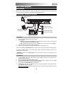
Rear Panel
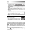
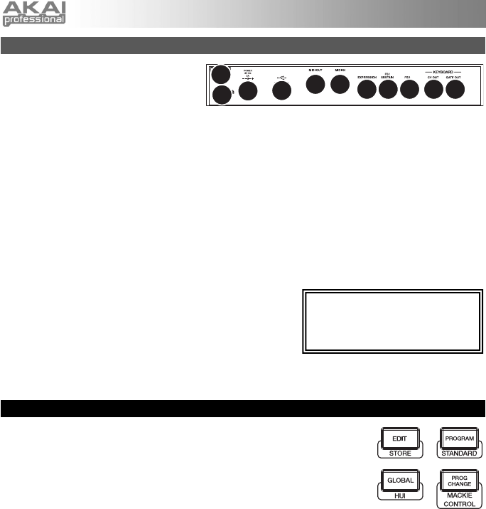
1. POWER INPUT – Connect the
included 6V DC – 1A power adapter
(center pin positive) to this jack then
into an electrical outlet. Using the
power adapter allows you to use MAX25's CV OUT and GATE OUT, and the touch faders will show a
full line of LEDs up to the current position (as opposed to a single LED when powered via USB).
2. POWER ADAPTER RESTRAINT – You can secure a power adapter cable to this restraint to prevent it
from accidentally unplugging.
3. KENSINGTON LOCK SLOT – You may use this Kensington lock slot to secure MAX25 to a table or
other surface.
4. USB PORT – Use the included USB cable to connect this port to the USB port of your computer.
MAX25 will be powered by your computer's USB connection. MAX25 is class-compliant, so it is "plug-
and-play" – no separate driver installation is necessary.
5. MIDI OUT – Use a five-pin MIDI cable to connect the MIDI OUT of MAX25 to the MIDI IN of an optional
external device.
6. MIDI IN – Use a five-pin MIDI cable to connect the MIDI OUT of an optional external MIDI device to the
MIDI IN of MAX25.
7. EXPRESSION PEDAL INPUT – Connect an optional 1/4" TRS expression pedal to this input.
8. FOOTSWITCH INPUTS – Connect an optional 1/4" TS footswitch to these inputs. If you are using a
sustain pedal, connect it to the FS1/SUSTAIN input.
9. *CV OUT – Use a 1/4" TS cable (not included) to connect
this output to an optional external sequencer to send
MAX25's control voltage (CV) data (0-5V, 1V/octave). The
data sent over this connection can be set in Global Mode.
Please also see the CV section of this manual.
10. *GATE OUT – Use a 1/4" TS cable (not included) to connect this output to an optional external
sequencer to send MAX25's Gate (trigger) data. The data sent over this connection can be set in
Global Mode.
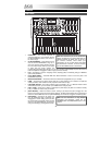
Modes
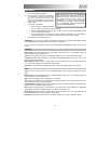
MAX25 has four different modes of operation. Each mode can be accessed by
pressing the corresponding button on MAX25.
In each page of each mode:
• Use the up/down CURSOR BUTTONS to move between settings on the
current page.
• Use the left/right CURSOR BUTTONS to move between different pages.
• Turn the VALUE DIAL to change the currently selected value/setting.
Following is a short description of each mode. Each mode is described in detail in its corresponding section
later in this manual.
[EDIT] Edit Mode: This mode allows you to edit the configuration of MAX25. Edit Mode is a powerful tool
for customizing your set-up. In this mode, you can make changes to how the keyboard, pads, touch faders
and other features behave. For example, you may want a touch fader to transmit only a limited range of MIDI
data, or you may want the pads to transmit on a different MIDI channel from the keyboard. You can change
these and other various parameters in Edit Mode. (See the Edit Mode Parameters section of the Appendix
for a summarized list of parameters.)
[PROGRAM] Program Mode: This mode allows you to load your stored Programs. A Program is a
collection of information about how the controls – keyboard, pads, touch faders, etc. – will behave (their
behavior can be adjusted in Edit Mode then stored). Using Programs allows you to save different
configurations, which can be quickly loaded when you need them, without having to reprogram MAX25 every
time.
[GLOBAL] Global Mode: This mode allows you to set global parameters and make general changes to
how MAX25 functions. For example, you can set the brightness of the LCD screen, the MIDI common
channel, MIDI clock settings, the pads' and keyboard's velocity curve and sensitivity, and more.
[PROG CHANGE] Program Change Mode: This mode allows you to transmit various Program Change
messages. In this mode, you can make your DAW or external device switch to a different program bank of
sounds. This way, you can switch between programs right from MAX25 rather than switching them manually
on your DAW or external device.
* The CV OUT and GATE OUT will
function only if MAX25 is connected
to a power source using the power
ada
p
ter.
1
2
3
4
56
7
88 910


