Chapter 3 Calibration Procedures
General Calibration/Adjustment Procedure
65
3
If the entered number is within an acceptable range, a "ENTERED" message
appears for one second. If the entered number is not correct, an "MIN VALUE"
or "MAX VALUE" message appears for one second and the display shows the
middle voltage calibration point again. The display now shows the high voltage
calibration point.
10
Read the DVM and change the first voltage value on the display to match
the measured voltage.
For example, if the DVM reads 28.995V, adjust the current to 28.995 V using the
knob and arrow keys.
11
Pressing the "Calibrate" key saves the new voltage calibration
constants, and goes to the OVP calibration mode.
A "CALIBRATING" message appears for one second to indicate that the voltage
calibration is progressing and new voltage calibration constants of "SETUP 1"
are stored. Then, the display shows above message to indicate that the power
supply is ready for the OVP calibration.
If the calibration fails, a "DAC CAL FAIL" or " ADC CAL FAIL" message appears
for one second and the display shows the "CAL SETUP 1" for voltage
calibration again.
Current and OCP Calibration
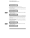
v hi 28.995 v
cal setup 2
Connect an appropriate shunt (0.01
9
) across the output terminals, and
connect a digital voltmeter across the shunt resistor for the current
calibration.
Calibrate


