


Front Panel Operation
86
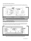
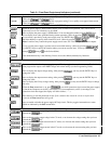
Table 5-1. Front Panel Controls and Indicators (continued)
ú ENTRY Keys (continued)
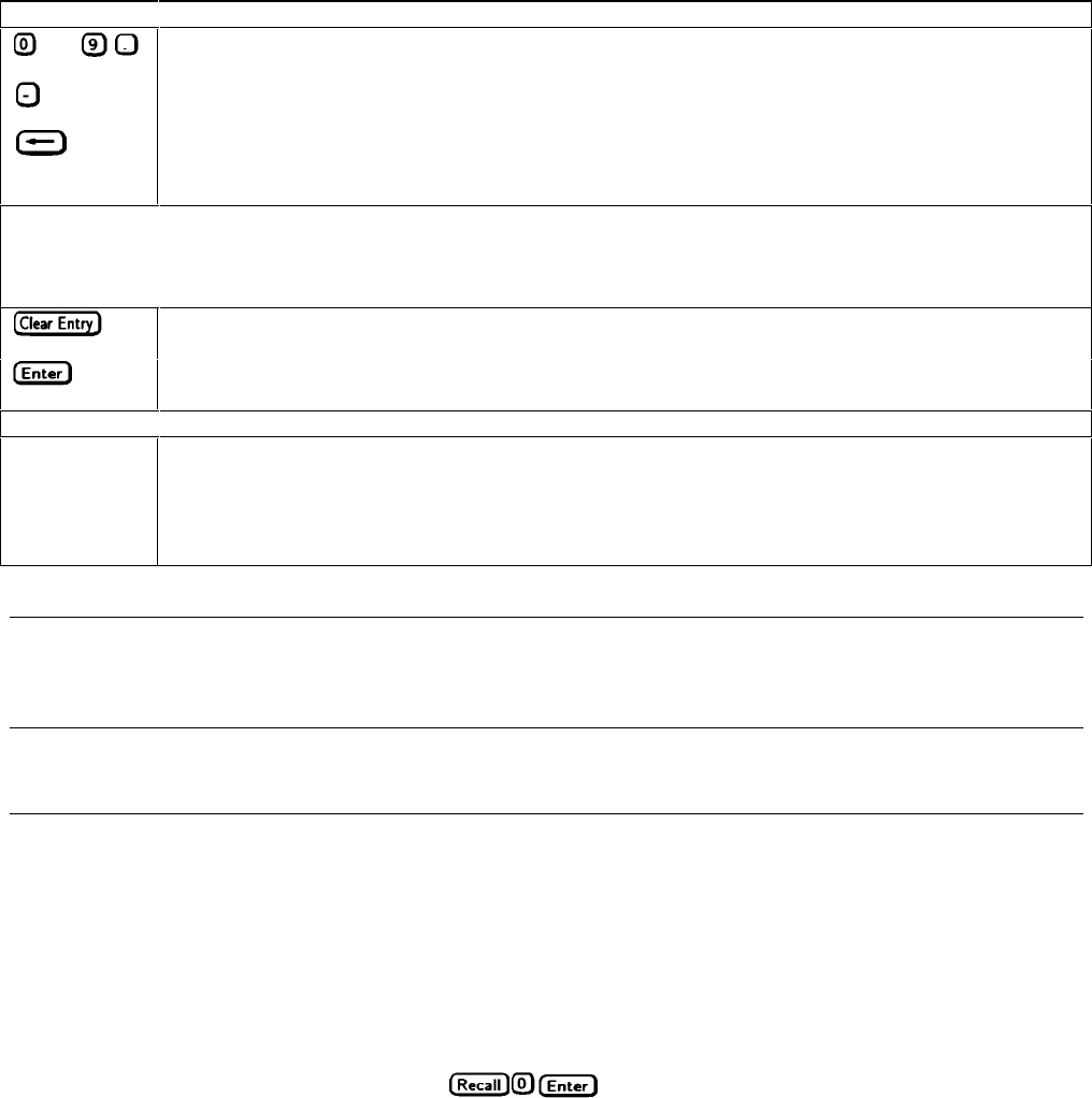
thru
Press to select numerical values .
Press to enter a minus sign.
Press to delete the last keypad entry. Use this key to remove one or more incorrect digits before they are
entered.
3
These four entry keys operate in two modes. Press and release for a single minimal change as
determined by the programming resolution (see Table 1-2 in Chapter l). Press and hold for an increasingly
rapid output change.
Press to delete an entire keypad entry and return to the meter mode. Use this key to exit from a value
before it is entered.
Press to enter a value or to accept an existing value and return the display to the meter mode.
The remaining shifted keys are for calibration (see "Appendix A - Calibration").
÷ Check Fuses LED and ø Dew LED (Series 668xA only)
Check Fuses
If one or more of the line fuses opens, this LED lights. (see "In Case of Trouble" in Chapter 3).
Dew
If you turn on the power supply when its inside humidity is ≈ 100%, the power will not go on and this
LED will light (see "In Case of Trouble" in Chapter 3).
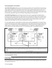
Programming The Output
Introduction
Important These instructions show how to program a single power supply. There are special considerations when
you have two or more supplies connected in series or in autoparallel. See "Chapter 4 - User Connections
and Considerations".
The power supply accepts values directly in volts and amperes. Values will be rounded off to the nearest multiple of the
output resolution (see “Average Resolution" in Table 1-2 of Chapter 1). If you attempt to enter a value not in a valid range,
the entry will be ignored and OUT OF RANGE appears on the display.
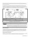
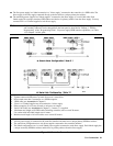
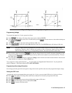
Figure 5-2 shows the general response of a typical power supply. Unless directed otherwise, always keep the output voltage
and current within the boundaries of its operating line for the specified mode of operation (CV or CC).
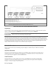
Establishing Initial Conditions
Set the power supply to its *RST state by pressing
. This state was stored in location 0 at the factory. If it
has since been changed, you can restore it as directed under “Turn-on Conditions”, later in this chapter. *RST results in the
following operating conditions:
■ Zero voltage output.
■ Minimal current output.
■ Output disabled (Dis annunciator on).
■ Overcurrent protection off (OCP annunciator off).
■ Protection circuits cleared (Prot annunciator off).