


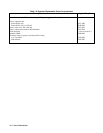
Turn-On Checkout 50
Power-On Checkout (All Models)
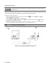
1. Connect the power cord to the power source (for Series 668xA, turn on the safety disconnect switch).
2. Turn the front panel power switch to ON (1).
3. For Series 668xA only, the Check Fuses and Dew LEDs should remain off. If either light is on or is blinking, go to
“In Case of Trouble” at the end of this chapter.
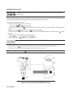
4. The power supply undergoes a self-test when you turn it on. If the test is normal, the following sequence appears on
the LCD:
a. Series 664xA/665xA - The GPIB address (factory default is 5).
b. Series 667xA/668xA - The GPIB address (factory default is 5). This is then followed by PWR ON INIT for
approximately 10 seconds.
5. The display then goes into the meter mode with the Dis annunciator on and all others off. “Meter mode” means that
the VOLTS digits indicate the output voltage and the AMPS digits indicate the output current. These values will be at or
near zero.
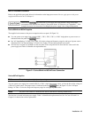
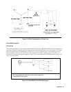
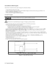
6. Verify that the power supply fan is on by placing your hand near the rear grill to feel the air flow. You may also be
able to hear the fan operating.
7. Press
once. The Dis annunciator will go off and the CV annunciator will go on .
Note If the power supply detects an error during self-test, the display will show an error message. Go to “In
Case of Trouble” at the end of this chapter.
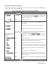
Using The Keypad (All Models)
Shifted Keys
Some of the front panel keys perform two functions, one labeled in black and the other in blue. You access the blue function
by first pressing the blue
key, which is not labeled. When the Shift annunciator is on, you will know you have access
to the key's shifted (blue) function.
Backspace Key
The
key is an erase key. If you make a mistake entering a number and have not yet entered it (have not pressed
), you can delete the number by pressing . You may delete as many numbers as you wish by repeatedly pressing
this key.
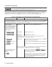
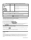
Output Checkout (All Models)
Important When the power supply is turned on, it asserts the state stored in EEPROM memory location 0.
For a new supply, this is the factory default (*RST) state. The following procedures assume that the
factory default state is still in location 0 (Turn-On Conditions in “Chapter 5 - Front Panel” for details).