


126 Current Loop Compensation (Series 668xA Only)
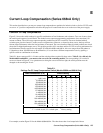
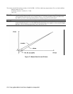
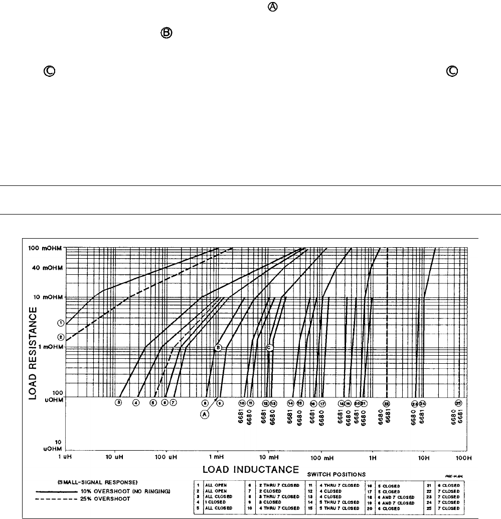
1 millihenry inductance and 100 micro ohms resistance (see point
) requires switch setting 9 (only switch 3 closed) to
obtain 10% overshoot. If the load resistance is increased to 1 milliohm, then the operating position will be to the left of the
existing compensation curve (see point
). This will result in a stable condition with less overshoot, but greater CV/CC
crossover time than if the curve defined by switch setting 8 were used. If the load resistance remains at 1 milliohm but the
load inductance increases to 10 millihenries, then the operating position will be far to the right of the compensation curve
(see point
). This results in a less stable condition with more overshoot. To obtain better operation at point , use the
compensation curve defined by switch setting 13 (Model 6680A) or 12 (Model 6681A).
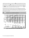
Most operating conditions will not fall directly on a curve and you will have to interpolate between curves. Generally,
moving to the left of a given curve increases stability. However, at large values of inductance the curves become almost
vertical because the load resistance has no effect on dampening the system. For Models 6680A and 6681A, the most stable
points are on the solid curves shown in Figure E-l. Points to the right or left of a curve will have more overshoot. Note the
two dashed vertical lines at switch setting 25 for Models 6682A, 6683A, and 6684A. Operation between these lines will
result in somewhat increased stability.
Note The best procedure is to test your settings under real operating conditions. For help in tailoring a specific
CC compensation, contact your Agilent Sales and Support Offices.
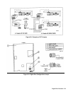
Figure E-1. CC Loop Compensation Curves for Models 6680A and 6681A