


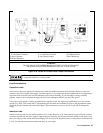

User Connections
68
Q=
L1
RCxtint eR+
where: C = model-dependent internal capacitance (see below); L = inductance of the load; Rext = equivalent series
resistance of the load; R
int
= model-dependent internal resistance (see below):
6671A 6672A 6673A 6674A 6675A
C=
44,000 µF 44,000 µF 12,000µF 7,000 µF 2,100 µF
R
int
=
1.8 mΩ 2.2 mΩ 4 mΩ 14 mΩ 30 mΩ
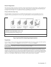
If the Q is greater than 0.5, inductive loads will ring with the output capacitance and will be damped according to the
following equation:
δ =
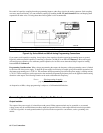
Battery Charging
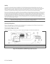
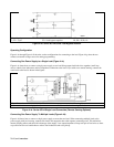
The power supply’s OVP circuit has a downprogrammer FET that discharges the power supply output whenever OVP trips.
If a battery (or other external voltage source) is connected across the output and the OVP is inadvertently triggered or the
output is programmed below the battery voltage, the power supply will sink current from the battery. To avoid this, insert a
reverse blocking diode in series with the ⊕ output of the supply. Connect the diode cathode to the + battery terminal and the
diode anode to the supply ⊕ output terminal. The diode may require a heat sink.
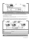
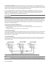
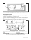
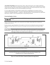
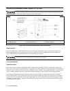
Local Voltage Sensing
Your power supply was shipped set up for local sensing. This means that the supply will sense and regulate its output at the
output terminals, not at the load. Since local sensing does not compensate for voltage drops across screw terminals, bus
bars, or load leads, local sensing should only be used in applications that require low output current or where load regulation
is not critical.
Local sensing is obtained by connecting the +LS sense terminal to the +S analog connector pin and the pin and the -LS
sense terminal to the -S analog connector pin. The power supply is shipped with these connections made.
Note If the sense terminals are left unconnected, the voltage at the bus bars will increase approximately 3 to 5%
over the programmed value. Since it is measured at the sense terminals, the voltage readback will not
reflect this increased output.
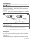
Remote Voltage Sensing
The dashed lines in the wiring diagrams illustrate remote voltage sensing. The remote sense terminals of the power supply
are connected directly to the load rather than to the output terminals. This allows the supply to automatically compensate for
the voltage drop in the load leads as well as to accurately read back the voltage directly across the load.
Setting Up Remote Sense Operation
Remote sensing is obtained by removing the jumpers connecting the +LS sense terminal to the +S analog connector pin and
the -LS sense terminal to the -S analog connector pin. The power supply is shipped with these jumpers connected.