


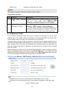
Configuration Procedure
Step Operation Description
1 Create VLANs Create three VLANs with the VLAN ID 3, 4 and 5 respectively,
and specify the description of VLAN3 as Multicast VLAN on
VLAN→802.1Q VLAN page.
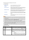
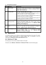
2 Configure ports On VLAN→802.1Q VLAN function pages.
For port 3, configure its link type as GENERAL and its egress rule
as TAG, and add it to VLAN3, VLAN4 and VLAN5.
For port 4, configure its link type as GENERAL and its egress rule
as UNTAG, and add it to VLAN3 and VLAN 4.
For port 5, configure its link type as GENERAL and its egress rule
as UNTAG, and add it to VLAN3 and VLAN 5.
3 Enable IGMP
Snooping function
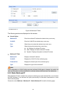
Enable IGMP Snooping function globally on Multicast→IGMP
Snooping→Snooping Config page. Enable IGMP Snooping
function for port 3, port4 and port 5 on Multicast→IGMP
Snooping→Port Config page.
4 Enable Multicast
VLAN
Enable Multicast VLAN, configure the VLAN ID of a multicast
VLAN as 3 and keep the other parameters as default on
Multicast→IGMP Snooping→Multicast VLAN page.
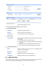
5 Check Multicast VLAN 3-5 and Multicast VLAN 3 will be displayed in the IGMP
Snooping Status table on the Multicast→IGMP
Snooping→Snooping Config page.
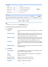
8.2 Multicast IP
In a network, receivers can join different multicast groups appropriate to their needs. The switch
forwards multicast streams based on multicast address table. The Multicast IP can be
implemented on Multicast IP Table, Static Multicast IP page.
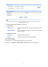
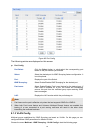
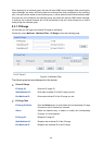
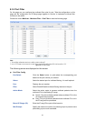
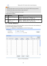
8.2.1 Multicast IP Table
On this page you can view the multicast IP table on the switch.
Choose the menu Multicast→Multicast IP→Multicast IP Table to load the following page.
83