


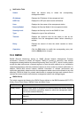
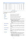
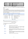
notifications 5
Normal but significant con
ditions
informational 6
Informational messages
debugging 7
Debug-level messages
Table 11-1 Log Level
The Log function is implemented on the Log Table, Local Log, Remote Log and Backup Log
pages.
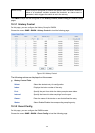
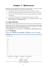
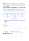
11.2.1 Log Table
The switch supports logs output to two directions, namely, log buffer and log file. The information
in log buffer will be lost after the switch is rebooted or powered off whereas the information in log
file will be kept effective even the switch is rebooted or powered off. Log Table displays the system
log information in log buffer.
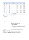
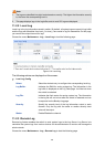
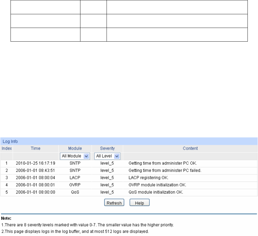
Choose the menu Maintenance→Log→Log Table to load the following page.
Figure 11-3 Log Table
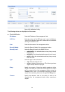
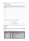
The following entries are displayed on this screen:
Log Info
Index: Displays the index of the log information.
Time: Displays the time when the log event occurs. The log can get the
correct time after you configure on the System ->System
Info->System Time Web management page.
Module: Displays the module which the log information belongs to. You can
select a module from the drop-down list to display the corresponding
log information.
Severity: Displays the severity level of the log information. You can select a
severity level to display the log information whose severity level value
is the same or smaller.
Content: Displays the content of the log information.
11
9