


1-3 (E)
DXF-51
24
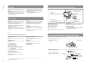
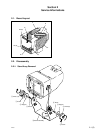
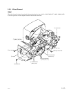
How To Attach and Connect the Unit to the Camera
3
Connect the 20-pin connector to the
camera’s VF connector.
to VF connector
VF connector cable
(20-piny26-pin)
25
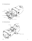
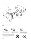
How To Attach the Viewfinder Hood
When using the viewfinder outdoors, attach the supplied
viewfinder hood to reduce glare.
Fix the hood tightening
screw.
Viewfinder hood (supplied)
26
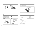
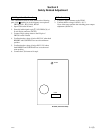
Operation
Turning on the camera or the camera control unit
automatically supplies power to the viewfinder. The
viewfinder image will appear within several seconds.
Adjust the viewfinder to the desired angle and height.
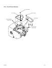
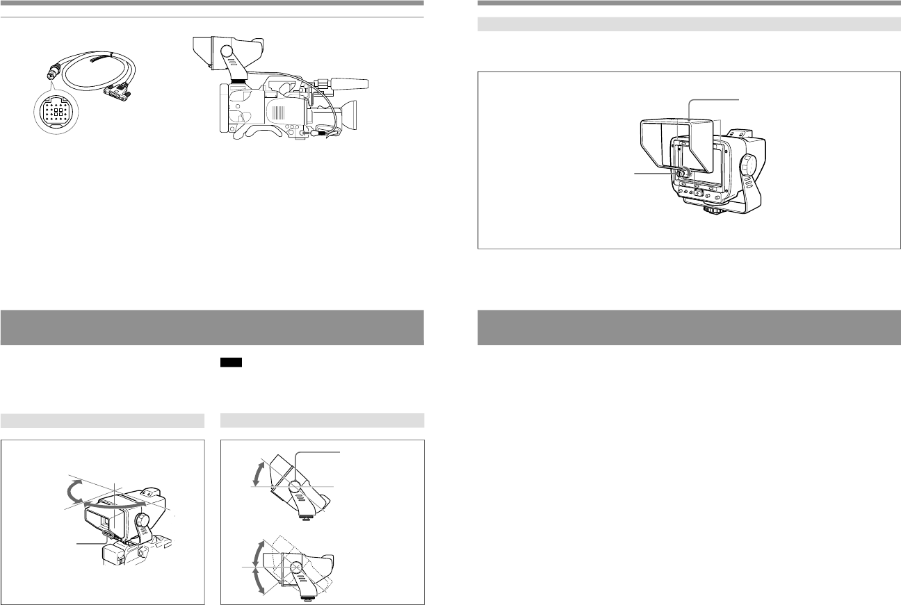
Panning
Note
When the BRIGHT control is turned fully counterclockwise,
no picture will appear on the viewfinder screen.
Tilting
For details, refer to the instruction manual supplied with the
camera or the CCU.
Adjust the controls
to give the best
possible picture.
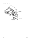
Loosen the LOCK screw
to adjust the angle of
the viewfinder that you
want. After you finished
the adjustment, tighten
the LOCK screw to fix
the angle.
90°
40°
90°
40°
40°
27
Specifications
Picture tube 5-inch monochrome
70-degree deflection
Video signal EIA standard/CCIR standard
Scanning system
2 : 1 interlace
525 lines
2 : 1 interlace
625 lines
Scan 5 % underscan
High voltage 8.5 kV
Horizontal resolution
More than 650 lines (at center)
Frequency response
10 MHz at –3 dB
Connectors Exclusive D-sub 26-pin connector
Video input: 1 V(p-p), sync negative,
3 kΩ
Power supply: 12 V DC
Power consumption
11 W
Operating temperature
0°C to +40°C (32°F to 104°F)
Dimensions Approx. 203 × 199 × 289 mm
(w/h/d) (8 × 7
7
/
8
× 11
1
/
2
inches)
including viewfinder hood
Mass Approx. 2.4 kg (4 lb 7 oz)
including viewfinder hood
Accessories supplied
Viewfinder hood (1)
VF connector cable
(20-piny26-pin) (1)
Number plate (1)
Operating Instructions (1)
Design and specifications are subject to change without
notice.