


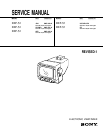

1 (E)
DXF-51
Table of Contents
1. Operating Instructions........................................................... 1-1 (E)
2. Service Informations
2-1. Board Layout.........................................................................................2-1 (E)
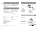
2-2. Disassembly ..........................................................................................2-1 (E)
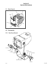
2-2-1. Stand Assy Removal ............................................................2-1 (E)
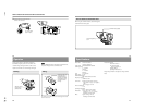
2-2-2. Bezel Assy Removal ............................................................2-2 (E)
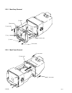
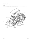
2-2-3. Back Cover Removal ...........................................................2-2 (E)
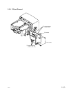
2-2-4. D Board Removal .................................................................2-3 (E)
2-2-5. G and P Boards Removal .....................................................2-4 (E)
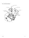
2-2-6. A Board Removal .................................................................2-5 (E)
2-2-7. Picture Tube and Q Board Removal ....................................2-6 (E)
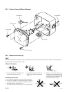
2-2-8 Removal of Anode Cap ........................................................2-6 (E)
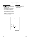
3. Safety Related Adjustment ................................................. 3-1 (E)
4. Electrical Adjustments
4-1. Preparation ............................................................................................4-1 (E)
4-2. Switching Power Output (RV501) Adjustment ....................................4-1 (E)
4-3. H.V. (RV302) High Voltage Adjustment .............................................4-1 (E)
4-4. H-HOLD (RV104) Adjustment.............................................................4-1 (E)
4-5. V-HOLD (RV103) Adjustment.............................................................4-1 (E)
4-6. V-DUTY (RV107) Adjustment.............................................................4-1 (E)
4-7. H-LEN (L302) Adjustment ...................................................................4-1 (E)
4-8. H-SIZE (RV301) Adjustment ...............................................................4-1 (E)
4-9. Heater Voltage Adjustment ...................................................................4-1 (E)
4-10. V-LIN (RV105) Adjustment .................................................................4-2 (E)
4-11. V-SIZE (RV109) Adjustment ...............................................................4-2 (E)
4-12. 16 : 9 V-SIZE (RV108) Adjustment .....................................................4-2 (E)
4-13. V-SIZE PAL (RV110) Adjustment.......................................................4-2 (E)
4-14. BRIGHT (RV102) Adjustment .............................................................4-2 (E)
4-15. FOCUS (RV111) Adjustment ...............................................................4-2 (E)
4-16. Deflecting Yoke Tilt Adjustment ..........................................................4-2 (E)
4-17. Centering Adjustment ...........................................................................4-2 (E)
5. Semiconductors................................................................................. 5-1