


KB3200 Series User’s Manual 5 - 3
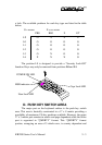
a lock. The available positions for each key type are listed in the table
below.
O = access X = no access
PRG REG Z GT
LP O X X X
L0 O O O O
L1 O O O O
L2 O O O O
L3 O X O O
L4 X X X O
The position L0 is designed to provide a “Security Lock-Off”
function. Keys may only be removed from positions L0 and L1.
CAPS LOCK
CAPS LOCK
POWER
POWER
NUM LOCK
NUM LOCK
MSR
MSR
LP
LP
L2
L2
L3
L3
L4
L4
L0
L0
L1
L1
7
7
8
8
9
9
4
4
5
5
6
6
1
1
2
2
3
3
0
0
00
00
.
.
Home
Home
PgUp
PgUp
End
End
PgDn
PgDn
Ins
Ins
Del
Del
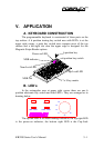
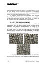
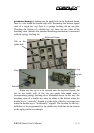
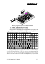
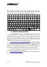
D. PUSH KEY SWITCH AREA
The major part on the keyboard surface is the push key switch
area. This area is basically constructed in a 17 x 8 matrix providing a
possibility of maximum 136 key positions available. However, the upper
17 x 3 matrix part remains in matrix and page dependent while the lower
part is organized in “QWERTY” format. This “QWERTY” format
portion, occupying an area of 5 whole rows, is country dependent and
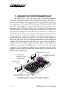
POWER ON LED
MSR indicator
Caps Lock LED
Num Lock LED