


KB3200 Series User’s Manual 5 - 1
V. APPLICATION
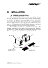
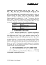
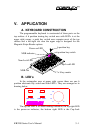
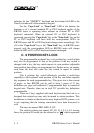
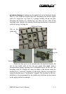
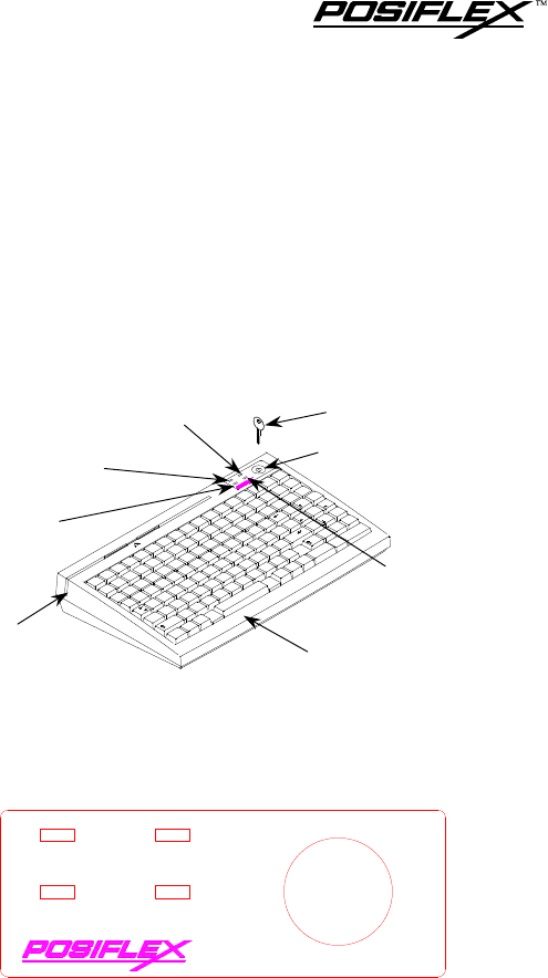
A. KEYBOARD CONSTRUCTION
The programmable keyboard is constructed of three parts on the
top surface. A 6 position turning key switch area with LED’s is at the
upper right corner, a push key switch area occupies most of the top
surface and a left-right slot near the upper edge is designed for the
Magnetic Stripe Reader options.
CAPS LOCK
CAPS LOCK
POWER
POWER
NUM LOCK
NUM LOCK
MSR
MSR
LP
LP
L2
L2
L3
L3
L4
L4
L0
L0
L1
L1
7
7
8
8
9
9
4
4
5
5
6
6
1
1
2
2
3
3
0
0
00
00
.
.
Home
Home
PgUp
PgUp
End
End
PgDn
PgDn
Ins
Ins
Del
Del
Enter
Enter
Shift
Shift
Ctrl
Ctrl
Ctrl
Ctrl
Alt
Alt
Alt
Alt
~
~
‘
‘
!
!
1
1
@
@
2
2
#
#
3
3
$
$
4
4
%
%
5
5
^
^
6
6
&
&
7
7
*
*
8
8
(
(
9
9
)
)
0
0
_
_
-
-
+
+
=
=
Shift
Shift
Caps
Caps
LOCK
LOCK
Tab
Tab
Q
Q
W
W
E
E
R
R
T
T
Y
Y
U
U
I
I
O
O
P
P
A
A
S
S
D
D
F
F
G
G
H
H
J
J
K
K
L
L
Z
Z
X
X
C
C
V
V
B
B
N
N
M
M
<
<
,
,
>
>
.
.
?
?
/
/
:
:
;
;
"
"
’
’
{
{
[
[
}
}
]
]
|
|
\
\
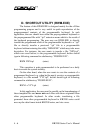
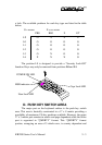
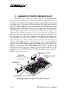
B. LED’s
In the rectangular area at upper right corner there are one 6
position electronic key switch and four LED’s. They are arranged as in
drawing below.
NUM LOCKNUM LOCK
MSRMSR
L3L3
L2L2
CAPS LOCKCAPS LOCK
POWERPOWER
LOLO
L1L1 LPLP
L4L4
TM
The top left LED is for MSR reading indication, the top right LED
is the power-on indicator, the bottom right LED is the Cap-Lock
MSR slot
MSR indicator
Power-on LED
6 position key
6 position key switch
17 x 8 key matrix
Caps Lock LED
Num Lock LED