


6 C561M-F (8/06)
OUTPUT WIRING
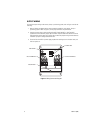
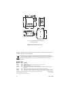
To install the output wiring to the camera, dome, or positioning system, refer to Figure 4 and do the
following:
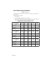
1. Refer to Table A and determine the output connection needed for your camera, dome, or
positioning system. Refer to Figure 4, for the proper connector strip connections.
2. Attach one output wire to either the Tap A (24 VAC), Tap B (26 VAC), or Tap C (28 VAC)
connections on the Secondary Output Tap’s connector strip and attach the second wire to the
COM connection on the same strip. Be sure that you have the proper wiring size and distances
installed if you plan to change connections later.
3. Close the lid to the WCS1-4 power supply, replace the retaining screw to the door latch, and
then turn power on.
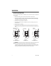
Figure 4. Wiring Connector Diagram
120V- F 1.6AH
240V- F 0.5AH
OUTPUT TERMINALS
SPARE FUSES
GROUND STUD
INPUT TERMINALS
FUSE HOLDER