FX1S Series Programmable Controllers Outputs 6
6-2
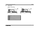
6.1 Relay Output Example
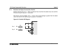
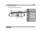
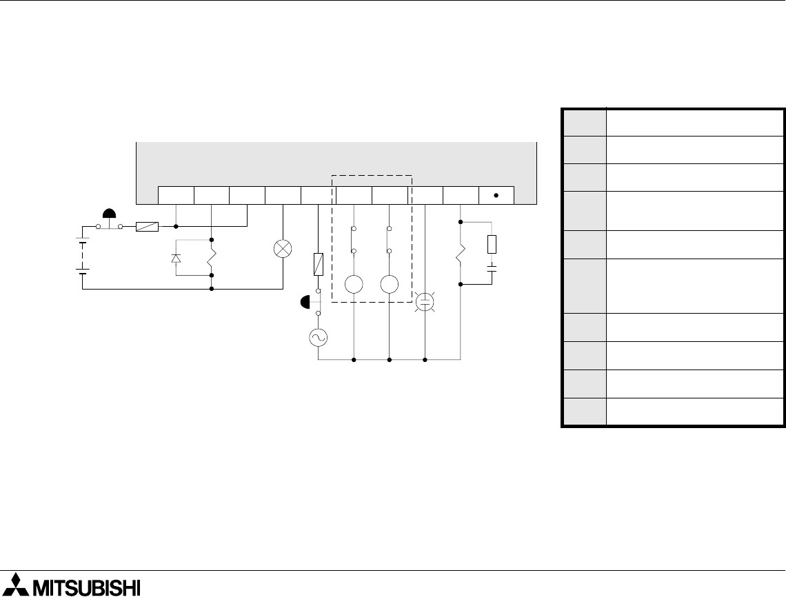
Figure 6.1: Typical Relay Wiring Diagram
n
nn
n
Do not use this terminal
o
oo
o
Fuse
p
pp
p
Surge absorbing Diode.
q
qq
q
External Mechanical
Interlock
r
Emergency Stop
s
Noise suppressor 0.1
µ
F
capacitor + 100-120
Ω
resistorContactor
t
Valve
u
Incandescent Lamp
v
DC Power Supply
w
AC Power Supply
COM0
Y0 Y1 Y2 Y3
COM1 COM2
Y4 Y5
MC1 MC2
➊
➏
➑
➍
MC2 MC1
➋
➎
➓
➐
➌
➋
➒
➎


