


Wiring 5-3
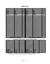
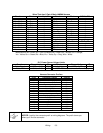
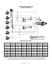
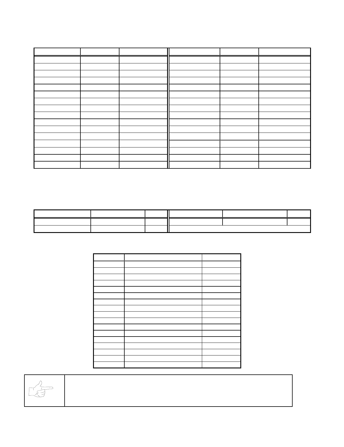
Wires That Aren’t Part of Main JAMMA Harness
Function Wire* Aux Adptr, P1- Function Wire* SIO Bd, P23-
Digital Ground Blk 1 Digital Ground Blk 1
Output Bit 0 Orn-Gry 2 Coin 3 Blk- Orn 2
Output Bit 1 Yel- Gry 3 +5 Volts Red 3
Output Bit 2 Blu- Gry 4 +12 Volts Orn 4
Output Bit 3 Vio- Gry 5 Unused Key 5
Unused NC 6 Coin 4 Blk-Yel 6
Unused NC 7 Dollar Bill Blk-Wht 7
Unused NC 8 Volume Down Orn-Red 8
Unused NC 9 Volume Up Orn-Grn 9
Unused NC 10 Unused NC 10
Unused NC 11 Unused NC 11
Unused NC 12
Function Wire Color* SIO Bd, P3-
Unused NC 13 +12 Volts Orn 1
Unused NC 14 Digital Ground Blk 2
Digital Ground Blk 15 Digital Ground Blk 3
-- -- -- +5 Volts Red 4
*
Abbreviations: Bd = Board; NC = Not Connected; Blk = Black; Brn = Brown; Orn = Orange;
Yel = Yellow; Grn = Green; Blu = Blue; Vio = Violet; Gry = Gray; Wht = White.
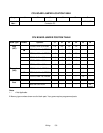
D.C. Power Source Voltage Limits
Function Range Limits ID Function Range Limits ID
Digital Circuits +4.90V to +5.10V +5V Audio, Lights -4.75V to -5.25V -5V
Audio, DBV +11.5V to +12.5V +12V NOTE: +5V is adjustable at the Power Supply
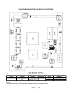
Harness Connector Prefixes
Prefix
Connector Location Example
1 CPU Board 1P1
2-- --
3 Sound / Interface (SIO) Board 3P1
4 Fluorescent Lamp 4P1
5 Power Supply 5P1
6 Video Monitor 6P1
7 Video Board 7P1
8 Coin Door Area 8P1
9 I40 Joystick Multiplexer Board 9P1
10 Auxiliary Output Adapter Bd 10P1
11 Cabinet 11P1
12 Hard Drive 12P1
13 Fans 13P1
14 Joysticks 14P1
15 Speakers 15P1
16 -- 16P1
17 -- 17P1
NOTICE:
Look for the connector prefix on wiring diagrams. The prefix shows you
where you’ll find the connector.