Software Developer’s Manual 383
General Initialization and Reset Operation
Default values for certain bits of the Device Control Register must be read out of the EEPROM and
appropriately set by software if an EEPROM is used.
Global Reset does NOT affect the direction of the software programmable pins.
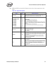
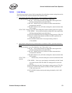
Link_Reset:
When LRST (bit 3 of the Device Control register) is written as a logic 1b, the Ethernet controller is
forced into a link reset state. When LRST is set to 1b the Auto-Negotiation function is disabled.
The Auto-Negotiation logic is initiated/restarted when LRST is transitions to 0b. A link reset is
only relevant in TBI mode/internal SerDes (not applicable to the
82540EP/EM, 82541xx and
82547GI/EI).
The transmitter sends /C/ ordered_sets when LRST is asserted.
General Registers: No change.
Interrupt Registers: No change.
Receive Registers: The RXCW register is cleared.
Transmit Registers: No change.
Statistics Registers: No change.
Wakeup Registers: No change.
Diagnostic Registers: No change.
PHY: No effect.
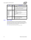
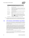
EE_RST (Extended Device Control Register):
EEPROM reset bit. Initiates a “reset-like” event to the EEPROM function that causes the
EEPROM to be read again. Control registers bits are not affected other than those read from the
EEPROM.
PHY_RST (Device Control Register):
PHY reset bit in the Device Control Register. By writing a 1b to this bit the software forces the
assertion of an internal signal output to reset the PHY device without accessing the PHY registers
through the MII management interface (MDI/O & MDC). Internal states of the Ethernet controller
are not impacted. To release the PHY reset the software must write a 0b to the bit.
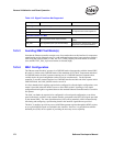
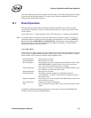
In situations where the Ethernet controller is reset using the software reset CTRL.RST, the TX data
lines are forced to all 0b’s. This causes a substantial number of symbol errors to be detected by the
link partner. In TBI mode/internal SerDes, if the duration is long enough, the link partner can
restart the Auto-Negotiation process by sending “break-link” (/C/ codes with the config register
value set to all 0b’s).
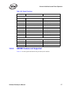
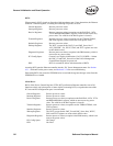
Some registers mentioned above within the Ethernet controller are treated specially. The RAH/
RAL[n], MTA[n], VFTA[n], WUPM[n], FFMT[n], FFVT[n], TDBAH/TDBAL, and RDBAH/
RDBAL registers have no default value and if the functions associated with the registers are
enabled they must be programmed by software. Once programmed, their value is preserved
through all resets as long as power is applied to the Ethernet controller. Bit 31, the valid bit, of the
RAH[n] registers is the exception and is reset with the LAN_PWR_GOOD and RST# and software
reset (CTRL.RST) bit.


