238 Software Developer’s Manual
Register Descriptions
13.4.7 MDI Control Register
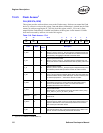
MDIC (00020h; R/W)
Software uses this register to read or write Management Data Interface (MDI) registers in the
internal PHY.
To read a location in the PHY, first perform an MDI write cycle with the following bit settings:
• Ready = 0b
• Interrupt Enable programmed to 1b or 0b
• Opcode = 10b (read)
• PHYADD = PHY address from the MDI register
• REGADD = Register address within the PHY to be read
When the serial data transfer from PHY to MAC is complete, the Ethernet controller issues an
interrupt if the MDI interrupt is enabled. The Ethernet controller also sets the Ready bit. This
indication tells the system that the read data is available from the 16-bit data field in the MDI
Control register. Perform a second read operation to the register at this time to recover the data.
To write a location in the PHY, perform an MDI write cycle with the following bit settings:
• Ready = 0b
• Interrupt Enable programmed to 1b or 0b
• Opcode = 01b (write)
• PHYADD = PHY address from the MDI register
• REGADD = Register address within the PHY to be written
• Data = Specific data for PHY operation
If enabled, the Ethernet controller issues an interrupt when the write completes. The Ethernet
controller also sets the Ready bit, denoting that a subsequent operation can be carried out.
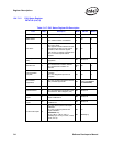
Note: The internal PHY register bit descriptions follow Table 13-14.


