


126 Software Developer’s Manual
FLASH Memory Interface
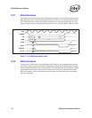
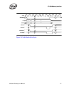
7.2.1 Read Accesses
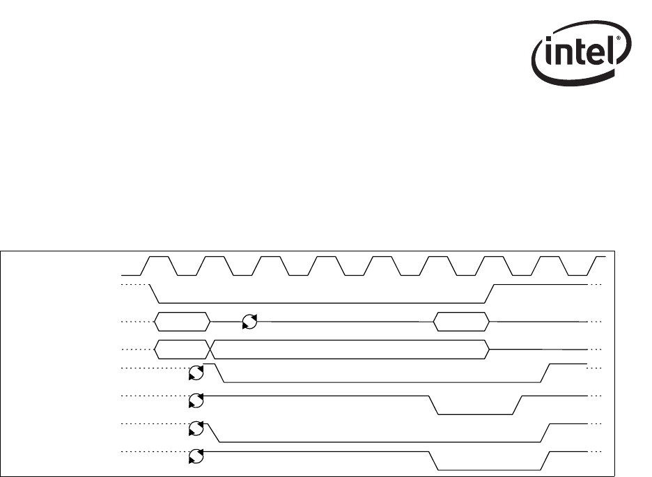
Upon reads to the FLASH address space, the Ethernet controller uses the TRDY# signal to insert
target wait states until valid data can be read from the FLASH device and presented on the data
lines. When TRDY# is asserted, the Ethernet controller drives valid data on the data lines. The
processor master can then complete normal data read cycle by asserting IRDY# when it is ready.
Figure 7-1. FLASH Buffer Read Cycles
7.2.2 Write Accesses
The processor, as the initiator, drives the address lines AD[63:0], the command and byte enable
lines [7:0]#, and the control lines IRDY# and FRAME#. It also provides the Ethernet controller
with valid data immediately after asserting TRDY#. The Ethernet controller controls the TRDY#
signal and deasserts it for a certain number of clocks until valid data is written to the FLASH
buffer. By asserting TRDY#, the Ethernet controller signals the processor that the current data
phase has completed.
CL
K
FRAME
#
AD
CBE
#
IRDY
#
TRDY
#
DEVSEL
#
STOP
#
1
2
3 4 5 6 7 8
ADDRESS
DATA
9
MEM-RD
BE#s