


Service
4 3A2097B
Service
Before Servicing
1. Flush system and follow Pressure Relief Proce-
dure in your ProMix Repair-Parts manual.
2. Close main air shutoff valve on air supply line and
on ProMix.
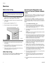
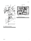
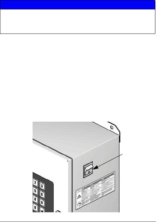
3. Shut off power (0 position). F
IG. 3.
4. Shut off power at main circuit breaker.
5. Disconnect all air and fluid lines from the flow con-
trol module.
6. Model 24H989 only: Disconnect all fluid lines from
the pressure sensor fitting (626).
7. Disconnect the flow control cable from the flow con-
trol harness (624). F
IG. 4 or FIG. 5.
After Servicing
After servicing, be sure to follow the Start Up checklist
and procedure in the ProMix Operation manual.
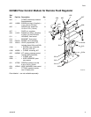
Servicing the Regulator and
Pressure Sensor (Model 249849
only)
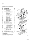
Regulator Service Kit 15G843 is available. Kit parts are
marked with an asterisk, for example (602*). For best
results, use all parts in the kit.
Sensor Service Kit 15G867 is available to service the
pressure sensor only. Kit parts are marked with a sym-
bol, for example (602‡). For best results, use all parts in
the kit.
1. Follow Before Servicing, above.
2. Remove the four screws (605) and the nut (601)
from the underside of the air plate (607). Separate
the air plate and fluid plate. F
IG. 4.
3. Unscrew the pressure sensor (620) from the fluid
plate (606).
NOTE: If you are only replacing the pressure sensor
kit 15G867, skip to step 6.
4. Remove the plug (615) and o-ring (604) from the top
of the fluid plate (606). Remove the parts of the dia-
phragm assembly (613, 610, 609, 612, 617, 616).
Remove and discard the dowels (623).
5. Reassemble the diaphragm assembly using the new
parts from the kit. Be sure the AIR SIDE of the dia-
phragm (617) faces down. Torque the nut (601) to
8-10 in-lb (0.9-1.1 N•m).
6. Install a new o-ring (602) on the pressure sensor
(620) and screw the sensor into the fluid plate (606).
7. Reinstall the fluid plate on the air plate. Be careful
not to pinch the pressure sensor cable. Torque the
screws (605) to 30-40 in-lb (3.4-4.5 N•m).
8. Reconnect the three cables to J1, J2, and J4 on the
circuit board (618). F
IG. 6.
9. Reattach the air plate (607) to the housing (611).
Torque the screws (605) to 30-40 in-lb (3.4-4.5
N•m).
10. Reattach the flow control cable and all air and fluid
lines.
NOTICE
To avoid damaging circuit board when servicing, wear
Part No. 112190 grounding strap on wrist and ground
appropriately.
F
IG. 3: Power Off
0 = OFF
TI12657a