


Crestron CPC-2000A Touchpanel with Dual Joysticks
Network Wiring
NOTE: This section only applies to those applications using 4-wire Cresnet wiring.
When calculating the wire gauge for a particular network run, the length of the run
and the power factor of each network unit to be connected must be taken into
consideration. If network units are to be daisy-chained on the run, the power factor
of each network unit to be daisy-chained must be added together to determine the
power factor of the entire chain. If the network unit is a home-run from a Crestron
system power supply network port, the power factor of that network unit is the
power factor of the entire run. The length of the run in feet and the power factor of
the run should be used in the resistance equation, shown below, to calculate the
value on the right side of the equation.
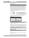
Resistance Equation
R = Resistance (refer to table below)
L = Length of run (or chain) in feet
PF = Power factor of entire run (or chain)
R <
L x PF
40,000
Where:
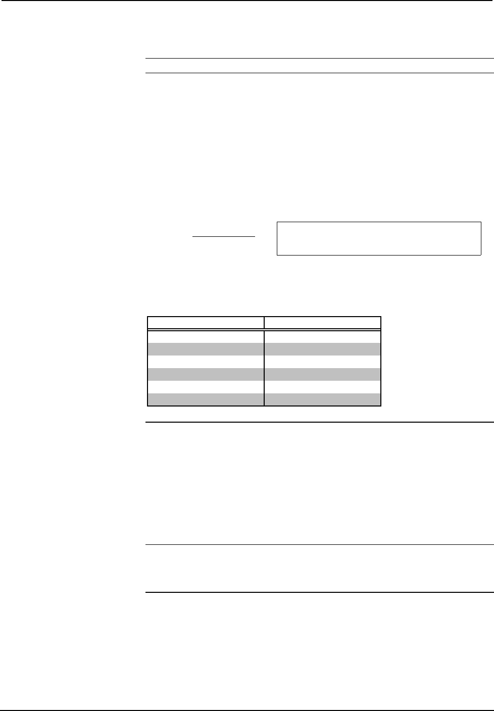
The required wire gauge should be chosen such that the resistance value is less than
the value calculated in the resistance equation. Refer to the table below.
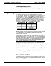
Wire Gauge Values
RESISTANCE (R) WIRE GAUGE
4
16
6
18
10
20
15
22
13
Doubled CAT5
8.7
Tripled CAT5
NOTE: All Cresnet wiring must consist of two twisted-pairs. One twisted pair is the
+24V conductor and the GND conductor and the other twisted pair is the Y
conductor and the Z conductor.
NOTE: When daisy-chaining Cresnet units, strip the ends of the wires carefully to
avoid nicking the conductors. Twist together the ends of the wires that share a pin on
the network connector, and tin the twisted connection. Apply solder only to the ends
of the twisted wires. Avoid tinning too far up the wires or the end becomes brittle.
Insert the tinned connection into the Cresnet connector and tighten the retaining
screw. Repeat the procedure for the other three conductors.
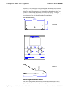
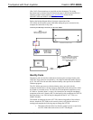
Hardware Hookup
WARNING: To avoid shock hazard and possible damage to the unit, do not use
touchpanel in rain or expose it to unnecessary moisture.
NOTE: The CN-RJ11 is not necessary if the CPC-2000A is connected directly to a
CNX-series control system.
NOTE: Before making any connections, review the latest revisions of the network
interconnection drawing (Doc. 5411) and the network modular cable requirements
Operations Guide - DOC. 5801A Touchpanel with Dual Joysticks: CPC-2000A • 5