


make adjustments before mounting the sight on the fi rearm. Be sure to check that the mount and the
sight remain fully secured after the fi rst 2 to 3 shots.
CAUTION-When a sudden increase in resistance in the adjustment screw is felt, the end of the
adjustment range has been reached. DO NOT try to turn the adjustments any further or damage
may occur to the sight.
8
9
BORE SIGHTING AND ZEROING
Bore sighting is a good preliminary procedure in achieving proper alignment of your sight to the fi rearm.
If the sight is to be mounted to a Weaver-style rail, it is imperative that the base be parallel to the bore.
Any major elevation adjustments may be accomplished by shimming the Weaver-style rail. It is important
not to use the elevation adjustment of the sight for major adjustments. The sight’s elevation and windage
adjustments should be used only for fi ne-tuning to achieve zero at the desired shooting distance. Final
zeroing of your fi rearm and sight should be done with live ammunition.
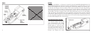
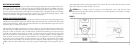
WINDAGE AND ELEVATION ADJUSTMENTS
The
Bushnell® Holosight® XLP has rotating adjustment features for elevation and windage adjustments.
The feature at the back of the sight is the elevation adjustment and the feature at the front side of the sight
is the windage adjustment. Both of the adjustment features have a slotted head that requires the use of a
screwdriver, coin, or similar tool to rotate.
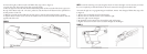
The elevation and windage adjustments are shown in Figure 5. For both elevation and windage, each
click will change the bullet’s point of impact 1/2 Minute of Angle (MOA), which translates to 1/4 inch at
50 yards, 1/2 inch at 100 yards. Also, one full rotation of either knob will change your point of impact
15 MOA. This translates into 8 inches at 50 yards, 15 inches at 100 yards. To move the point of impact
UP, turn the adjustment counterclockwise; to move the point of impact DOWN, turn the adjustment
screw clockwise. To move the point of impact RIGHT, turn the adjustment screw counterclockwise;
to move the point of impact LEFT, turn the adjustment screw clockwise. The elevation and windage
adjustments have been initially set at the factory near the midpoint of their adjustment ranges as well as
parallel to the rail, and should be close to zero with a properly installed sight and mounting rail. Do not
FIGURE 5