


Overview
1-3
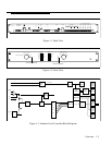
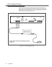
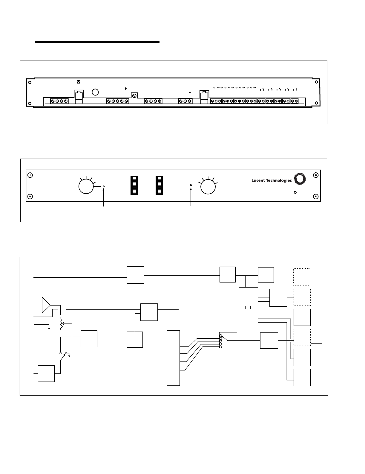
Figure 1-1. Back View
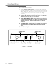
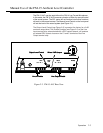
Figure 1-2. Front View
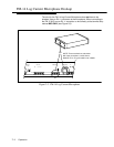
Figure 1-3. Ambient Level Controller Block Diagram
-24dB -24dB -18dB -12dB -6dB
NO C
1
NO C
1
NO C
1
NO C
1
NO C
1
NO
1
NO
1
NO
1
NO
1
C
NC
C
NC
C
NC
C
NC
Power Input
24 Volts AC
Telco In
Loop Start
Line In
C1 G
+ -
Output
Level
Line Out
+ -
C1 C
Mic Only
Mic Only
Relay Outputs
Clock Inputs or Remote Control
Shield
Model FM-15
100dB
90dB
80dB
70dB
60dB
105dB
95dB
85dB
75dB
65dB
Full Volume
-6 dB
-12 dB
-18 dB
-24 dB
Noise Level
dB SPL
Paging Level
dB
-18 dB
-24 dB
-12 dB
-6 dB
Manual Level Control
Power
95dB
90dB
100dB
105dB
Set Maximum Noise Level
Automatic Level Control
Telephone Input Active
85dB
4 to
20 Mil
Rec.
X 1 Buffer
Clock
Inputs
4 Volume
Control
Over-rides
for High
Noise Level
600 Ohm
Bal line
Driver
AGC
Audio
Detect
Gain Hold
0 dB
-6
-12
-18
-24
LED
Driver
LED
Display
4 Bit
Converter
Micro
68HC705
4 Bit
Converter
X 1 Buffer
or Level
Set
Clock
Inputs
FP Manual
or Automatic
Level
Control
Selection
600 Ohm
Bal line
Driver
FP
Selector
for Max.
Noise
FP PA
Level
Display
One of 8
0 to 5 Volt
0 DBM
C1
G
Loop St