


CL6700 User Manual
6
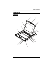
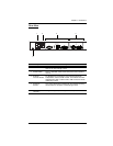
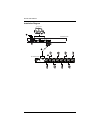
No. Component Description
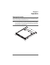
1 Upper Handle Pull to slide the LCD module out; push to slide it in.
See Opening the Console, page 13, for details on sliding the
console in and out
2 Module Release
Catches
In order to slide the console out, you must first release it by
sliding these catches to the inside.
3 LCD Module After sliding the LCD module out, flip up the cover to access
the LCD display.
4 LCD Controls The buttons to control the position and picture settings of the
LCD display are located here. See page 16, for details.
5 LCD On / Off
Button
Push this button to turn the LCD monitor on and off. The
button lights when the LCD monitor is off.
Note: The light indicates that only the monitor is off, not the
attached KVM switch.
6 Keyboard Module Standard 105-key keyboard
7 Touchpad Standard mouse touchpad
8 USB Port The USB port is available to connect a USB peripheral
device (flash drive, CD-ROM drive, etc.) to the console, or a
USB mouse for users who prefer to use an external mouse.
9 Power LED Lights (blue) to indicate that the unit is receiving power.
10 Rack Mounting
Tabs
Rack mounting tabs are located at each corner of the unit.
See Standard Rack Mounting, page 9, for details.
11 Lock LEDs The Num Lock, Caps Lock, Scroll Lock LEDs are located
here.
12 Reset Switch Located to the right of the Lock LEDs. Press this recessed
switch in with a thin object to perform a system reset.
13 Firmware
Upgrade Port
The firmware upgrade cable that transfers the firmware
upgrade data from the administrator’s computer plugs into
this RJ-11 connector.
14 Firmware
Upgrade Switch
During normal operation and while performing a firmware
upgrade, this switch should be in the NORMAL position. If a
firmware upgrade operation does not complete successfully,
this switch is used to perform a firmware upgrade recovery.
See Firmware Upgrade Recovery, page 27, for details.