


User Connections
78
Connecting Supplies in Auto-Parallel
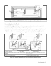
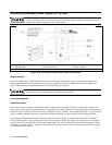
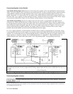
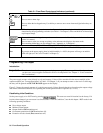
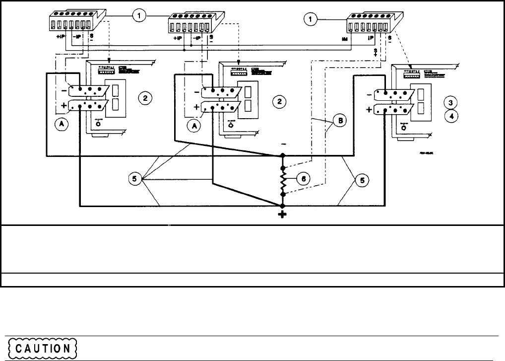
Auto-Parallel Wiring (Figure 4-5e). Figure 4-5e shows how power supplies can be auto-paralleled for increased current
output. Up to three supplies can be connected for auto-parallel operation. Use heavy enough load leads so that the absolute
voltage difference between the ⊕ output terminals of the "master" supply and the ⊕ output terminal of the first "slave"
supply is kept under 2 V at rated current. This also applies to the voltage difference between the ⊕ output terminals of the
first and second "slave" supplies. If remote sensing is necessary, connect the remote sense terminals of the "master" supply
as shown by the dashed lines in Figure 4-5e. See "Remote Voltage Sensing" for more information.
Auto-Parallel Programming. Only the first supply in the series (the "master") is programmed; the supplies that are
connected to the master automatically track its output. However, the voltage and OVP settings of the slave supplies must
be set higher than the operating voltage of the master supply. This ensures that the slave supplies will operate in CC mode
when tracking the output of the master supply. Be sure to set the output current of the slave supplies to zero, because all
current programming inputs (GPIB, front panel, and external voltage) are additive. Functions such as status, voltage
readback, and current readback can still be read back individually for each supply.
If a "slave" supply experiences a desired shutdown condition (such as caused by overtemperature or overcurrent), it does
not automatically shut down all other supplies. You must first enable remote inhibit (RI) and discrete fault indicator (DFI)
operation. It is recommended that you use the RI and DFI functions to automatically shut down all supplies whenever one
supply experiences a shutdown condition. See "Fault/Inhibit Operation" in "Appendix D - Digital Port Functions" for
wiring information and "Questionable Status Group" in the "Programming Guide" for programming information.
Analog Connector ó Slave Supply ì Master Supply
öProgram only the master. Set slave output and OVP voltage slightly higher than the master to ensure that slave stays in
CC mode
ú Load
÷ Load Connection
A Only local sensing permitted
B
Connect for remote sensing (optional)
Figure 4-5e. Series 668xA Auto-Parallel Connection (Remote Sensing Optional)
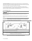
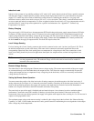
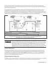
Connecting Supplies in Series
Floating voltages must not exceed ± 60 Vdc. No output terminal may be more than 60 V from chassis
ground.
Figure 4-5f illustrates how power supplies can be connected in series for increased voltage capability. Series connections
are straightforward in this case.