


Using Agilent 668xA Series Power Supplies in Autoparallel 129
F
Using Agilent 668xA Series Power Supplies in Autoparallel
This information is supplementary to the information on page 80.
A maximum of three Agilent 668xA series power supplies having the same model number, may be configured for
autoparallel operation. The Agilent 668xA power supplies were designed with an external programming offset so that the
master unit will output current before the slave units do. Therefore, slave supplies will always sink current when low output
current values are desired.
Autoparallel Procedure
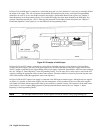
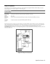
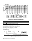
1. Connect the Agilent 668xA power supplies with the Im terminal from the master connected to the +Ip terminal of each
slave. Connect the ÏP terminal of the master to the -Ip terminal of each slave (see Figure 4-5e on page 81).
2. Each load lead should be of the same wire gauge and length.
3. Turn on all power supplies.
4. Program each slave supply for zero (0) output current either by pressing [CURRENT ] [0] [ENTER] from the front panel
keypad or sending the command "CURR:LEV 0" via the GPIB (see notes 2 and 3 on the follwing page).
5. Program each slave’s output voltage at least 2 volts higher than the output voltage that the master supply will be
programmed to.
6. Program the master supply’s output current for a value slightly greater than one-half of the total desired output current if
there is one slave supply, or one-third of the total desired output current if there are two slave supplies.
7. Enable all power supplies by pressing the [Output On/Off ] key.
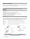
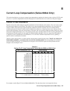
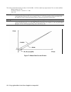
8. Increase the master supply’s output voltage. At low output currents, the master unit will be supplying all of the load
current and the slave supplies will be sinking current, which is normal. At maximum output current each supply will be
delivering an equal amount of output current. When operating at less than maximum current, it is normal to have unequal
current sharing between the master and slave supplies. Current sharing among the supplies only becomes equal at
maximum output current (see Figure F-1 ).
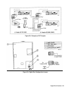
9. For remote sensing, connect only the master supply’s +S and -S lines. Slave supplies should be connected for local
sensing at the rear of their respective output terminals.
Note 1 The current division between the master and slaves can be determined as follows:
Iout=Im [ 1 +Ns ( 1 +0.127V/5V)] - Ns Ifs (0.127V/5V)
The amount of current the master unit must output before the slave units will output current can be determined as follows:
Ns * Ifs (0.127V/5V)
where Im = master current
Ns = number of slaves
Ifs = full scale current
Example: 1 master unit, 2 slave units, Agilent Models 6680A (5V, 875A)
Iout = Im ( 3.0508 ) - 44.4A