27
Pressure
Natural Gas cookers 20mbar.
For LP Gas cookers 29mbar for Butane and
37mbar for Propane.
After checking the pressure, turn the taps off and
replace the burner head.
Electrical Connection
WARNING: THIS COOKER MUST BE EARTHED.
All external wiring must comply with the IEE
Regulations for the Electrical Equipment of
Buildings. Connection to the electrical supply can be
made with either a plug and socket or be
permanently wired via a double pole switch. The
cooker is supplied with a 3 core cable 2m long. If a
replacement cable is fitted it must be 250v high
temperature PVC (85°C), 1mm
2
. Should the plug not
fit the socket in your home, it should be removed
and replaced with a suitable plug. Note: If a plug is
fitted which is not suitable, it must be cut off and
disposed of properly. To avoid the risk of
electrocution, the plug must not be left where
children might find it and plug it into a supply
socket.
Three pin plugs to BS1363 with a capacity of not less
than 13A must be used and fitted with a 13 amp fuse
‘ASTA’ approved to BS 1362.
After replacing the fuse the cover must be refitted. If
the cover is lost, the plug must not be used until a
replacement cover has been obtained from your
supplier. The colour of the correct fuse carrier is that
of the coloured insert in the base of the fuse recess,
or stated elsewhere on the plug. Always state this
colour when ordering a replacement fuse carrier.
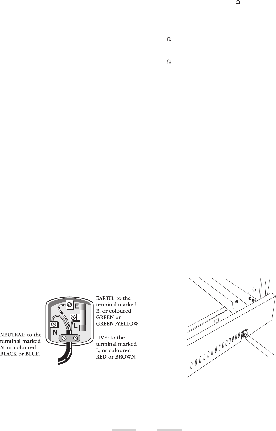
IMPORTANT The wires in the mains lead are
coloured in accordance with the following code:-
GREEN AND YELLOW: EARTH
BLUE: NEUTRAL
BROWN: LIVE
The wires should be connected into the terminal of
your plug as shown:
Electrical checks
EARTH CONTINUITY CHECK
The cooker must be disconnected from the power
supply. Set your meter to (ohm) on the X1 scale
and adjust to zero if necessary.
Test the leads from any of the cooker’s earth points
(e.g. inside electric box cover) - to the earth pin on
the cooker’s plug - resistance should be less than
l (ohm). If it is not, check all the earth wires for
continuity. Check that all contacts are clean and
tight. Re-check. If the resistance is still greater than
l (ohm) there may be a problem, consult a
qualified electrical engineer.
POLARITY CHECK
The cooker must be connected to the power supply.
Your meter should be set on 300V ac scale.
Test at the cooker terminal block:
1. Test leads from L to N. Your meter should read
approx. 220-240V ac.
2. Test leads from L to E. Your meter should read
approx. 220-240V ac.
3. Test leads from N to E. Your meter should read
approx. 0-15V ac.
If the readings are different from these values there
is an electrical fault. Rectify any fault and repeat the
test. If necessary repeat the test at the supply system
socket/spur - if the fault also occurs at this stage then
there is a house system fault which requires
attention by the Electrical Authority.
The customer should be warned NOT to use the
appliance until this examination has been carried
out.
Fitting the plinth
Loosen the 3 screws along the front bottom edge of
the cooker. Hook the central keyhole over the
central screw. Twist and fit each end keyhole over
their respective screws. Tighten the fixing screws.


