5.3.2 VLAN setting example:
-5 appears and Table 5-2 describes the port configuration of switch.
5.3.2.1 Two separate VLAN
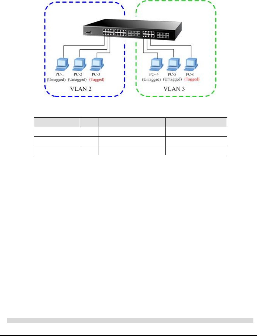
The diagram shows how the switch handle Tagged and Untagged traffic flow for two VLANs. VLAN Group 2 and VLAN
Group 3 are separated VLAN. Each VLAN isolate network traffic so only members of the VLAN receive traffic from the
same VLAN members. The screen in Figure 5
Figure 5-5 two separate VLAN diagram
VLAN Group VID Untagged Members Tagged Members
VLAN Group 1 1 Port-1,Port-2 Port-3
VLAN Group 2 2 Port-4,Port-5 Port-6
VLAN Group 3 3 Port-7~Port-24 N/A
Table 5-2 VLAN and Port Configuration
The scenario described as follow:
Untagged packet entering VALN 2
1. While [PC-1] transmit an untagged packet enters Port-1, the switch will tag it with a VLAN Tag=2. [PC-2] and
[PC-3] will received the packet through Port-2 and Port-3.
2. [PC-4],[PC-5] and [PC-6] received no packet.
3. While the packet leaves Port-2, it will be stripped away it tag becoming an untagged packet.
4. While the packet leaves Port-3, it will keep as a tagged packet with VLAN Tag=2.
Tagged packet entering V
5. While [PC-3] transmit a tagged packet with VLAN Tag=2 enters Port-3, [PC-1] and [PC-2] will received the
6. While the packet leaves and Port-2, it will be stripped away it tag becoming an untagged packet.
, the switch will tag it with a VLAN Tag=3. [PC-5] and
ile the packet leaves Port-6, it will keep as a tagged packet with VLAN Tag=3.
LAN 2
packet through Port-1 and Port-2.
Port-1
1. While [PC-4] transmit an untagged packet enters Port-4
Untagged packet entering VLAN 3
[PC-6] will received the packet through Port-5 and Port-6.
2. While the packet leaves Port-5, it will be stripped away it tag becoming an untagged packet.
3. Wh
#Notice:
At this example, VLAN Group 1 just set as default VLAN, but only focus on VLAN 2 and VLAN 3 traffic flow.
EM-GSW2416SFv1 - 39 -


