Installation
3-3
Part 1061253B
E 2006 Nordson Corporation
Electrical Installation Guidelines
Power Line Connections
Refer to Table 3-1. This unit is designed to
accommodate a broad range of power line voltages
for both 50 and 60 Hz found around the world. The
power line input is three phase, and the
transformer taps must be changed to select the
operating voltage range. The power supplies are
designed to operate at
+
/
-
10% of the normal
voltage for a given tap setting. Only the taps on the
two identical power transformers need to be
changed.
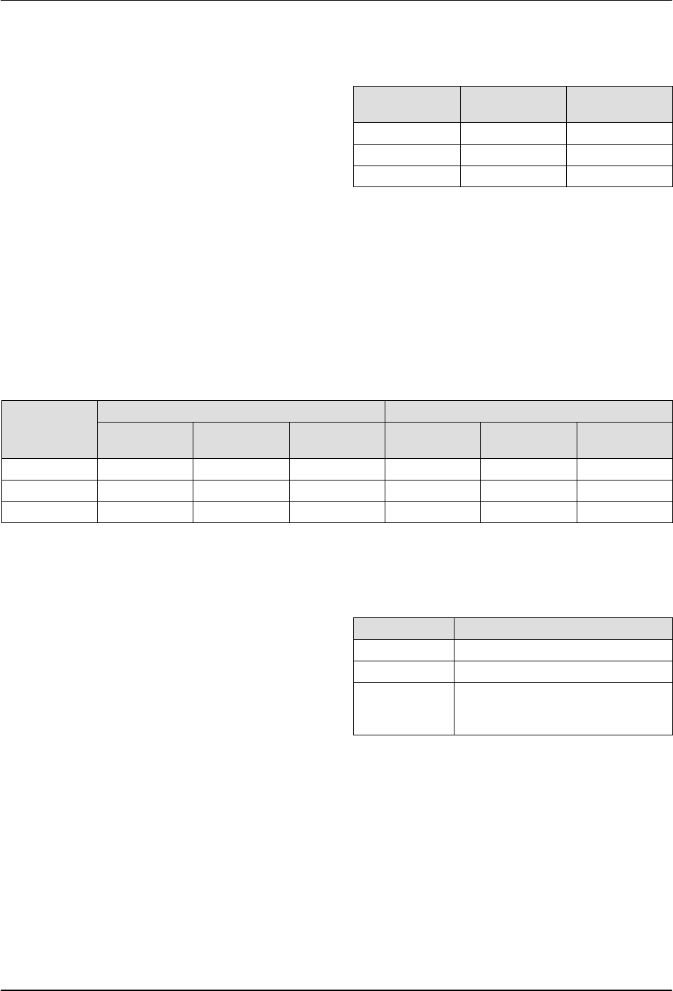
Table 3-1 Transformer Taps
Normal
Voltage
Voltage
Range
Transformer
Tap
480
+
/
-
10% 432-528 480
440
+
/
-
10% 396-484 440
380
+
/
-
10% 342-418 400
Input Power Configuration
Refer to Table 3-2. Current ratings indicate current
demand during normal full-power operation. Size
supply wiring and circuit breakers or fuses to allow
for heavy current draw during startup.
Table 3-2 Power Line Current
Line
60 Hz 50 Hz
Amps @
380 Vac
Amps @
440 Vac
Amps @
480 Vac
Amps @
380 Vac
Amps @
440 Vac
Amps @
480 Vac
L1 14 13 12 16 15 14
L2 22 21 18 25 23 21
L3 13 13 12 16 15 14
Power Source
The customer power source must be wired in
accordance with either the National Electric Code,
Part I or the Canadian Electrical Code, Part I, or
local codes.
Connector P1 on the power supply is for
three-phase input power. A 600 Vac, 30 Amp twist
lock connector is supplied with the system for the
power input.
Measure the incoming power source voltage from
the main power supply. Make sure that the power
source voltage matches the transformer tap
settings.
Environmental Operating
Conditions
Condition Specification
Altitude Up to 2000 meters (6561 ft)
Temperature
5-40 _C (41-104 _F)
Rh
80% up to 31 _C (88 _F),
decreasing lineraly to 50%
at 40 _C (104 _F).


